COMPUTATION OF ALUMINUM REDUCTION CELL
ENERGY BALANCE
USING ANSYS® FINITE ELEMENT MODELS

Marc Dupuis
GéniSim
3111 Alger St.
Jonquière, Québec, Canada G7S 2M9
e-mail:

Abstract

Over the last ten years, the industry standard for modeling aluminum reduction cell energy balance went gradually from 2D «in-house» codes to 3D commercial codes, like the ANSYS® finite element code. In this transition, many different modeling tools have been developed: 3D cathode slice, half anode, full cell slice, cathode corner/quarter and full cell corner/quarter models.

In this paper, advantages and disadvantages of each of those 3D models as well as basic assumptions are reviewed and the 2D model is revisited to introduce a new improved approach.

Introduction

The thermo-electric design of an aluminum reduction cell is the aspect of cell design which has the most influence on the cell power consumption expressed in terms of kWh/kg of aluminum produced. It is also one of the key elements affecting the cell lining life. Because of this important impact on cell lining life, the thermal balance of the cell is often the limiting factor which prevents smelters to increase production by increasing line amperage.

For those reasons, the cell thermo-electric design is a major element affecting the bottom line profitability of smelters operation. On the other hand, it is also an aspect of cell design that is not expensive to modify in a smelter retrofit project. So, improving the cell thermo-electric design has clearly the potential of bringing the fastest return on investment in continuous improvement projects of most smelters.

Some history of thermo-electric models development

Unfortunately, the Hall-Héroult aluminum electrolysis process is very complex as it involves many different physical and chemical phenomena; not all very well understood and often interacting with each other[1]. This means on one hand, that design improvement by trial and error in smelters is not a practical solution, and, on the other hand, that developing reliable models to perform theoretical analysis is not easy.

Yet over the years, valuable mathematical modeling tools have been developed. Historically, the aluminum companies started by developing «in-house» computer programs. The implemented mathematical models were typically 2D thermal models with «assumed» source terms to account for the Joule heat production[2].

The finite element method (FEM) was often the preferred numerical formulation because it offered the possibility to mesh the complex cell lining geometry without deforming it[3].

The next improvement was the addition of a second differential equation to solve the electric potential to make the model truly thermo-electric[4]. Yet, trying to represent the thermo-electric behavior of an aluminum reduction cell with a 2D model is not an easy task because the path of current through anode studs and cathode collector bars is truly three dimensional in nature. The 2D geometry of the model typically forced the representation of round studs and rectangular collector bars as continuous plates.


This is why the next logical step was to produce 3D models[3]. Most of the time, the transition to 3D models also means the transition toward commercial software since the scope of developing a generic user-friendly FEM thermo-electric code exceeded the limited resources of «in-house» code developers.

The commercially available FEM code ANSYS® offered the required thermo-electric capabilities needed to build 3D thermo-electric models.

When the author joined the Alcan Research Center in Jonquière in 1984, he was given the mandate to develop a 3D half anode thermo-electric model using ANSYS®[5]. The next year, he developed a 3D cathode slice model followed by a 3D cathode corner model[6] which included an extra convergence loop to compute the position of the ledge profile[7]. The main drawback of those models was that they required enormous computer resources. As an example, the very first model built ran for two weeks elapsed time on a VAX 780!

At the time, developing a complete 3D cell slice model that would have been the natural extension of existing 2D models was clearly not an option. Solving independently the anode and the cathode parts is a good modeling approach. The author expands on that in the next section of this paper and in his TMS industrial aluminum electrolysis course notes[1].

As computer resources started to become more available, it was possible to expand the 3D cathode slice model into a full quarter cell model[8,9]. At the same time, the extra ledge convergence loop that was initially developed to run on a VAX platform was recoded to be incorporated directly in ANSYS® by using the ANSYS® parametric design language (APDL) which means that the same model could be run on any computer platform.

The availability of faster computers also permitted the development of 3D thermo-electric cell slice models[10,11]. It is now possible to develop full

thermo-electric corner/quarter cell model[12] and even coupled 3D magneto-hydrodynamic(MHD) and thermo-electric quarter cell model[13]. Unfortunately, the author thinks that the last two models mentioned still require too much computer resources to be consider as «practical» design tools today, maybe like the 3D half anode model was in 1984!

Considering the number of modeling options now available, the scope of this paper is to compare the relative merits of these 3D thermo-electric models to perform retrofit studies. The 2D model is also revisited to introduce a new improved approach.

3D thermo-electric half anode model

The 3D half anode model is quite efficient in the computation of the anode panel heat losses and the anode drop. The model takes advantage of the natural right/left symmetry that exists when the anode is away from the cell corner and the effect of the anode change pattern is neglected. The anode is modeled at mid-life with a typical layer of cover material (see Figure 1).
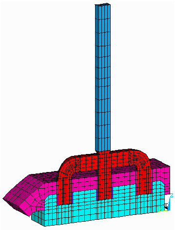
Figure 1: Half anode model mesh
In order to separate the anode from the cathode, the side crust must be cut somewhere. The author usual approach is to cut from the top crust/side block edge to the internal ledge profile at the bath surface level. This typically creates a cut that is close to a 45° angle and almost perpendicular to the crust surface. This procedure generates a cutting plane which represents an almost adiabatic surface and introduces no significant error in the model.

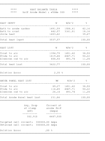
Of course, in such a model, the cell operating temperature has to be defined as an input to the model. As the result, the model will compute the heat losses that correspond to the thermal gradient between the operating temperature and the defined air temperature under the hood considering the global thermal resistance of the covered anode assembly (see Table 1).

Table 1: Half anode model heat balance table

The advantage of this approach is that the anode design study can be carried out separately from the

cathode design. The disadvantage is that the model only gives the anode panel heat losses as a result. This means that the user will eventually have to add the heat loss results of the cathode model result and then compare the sum with the independently computed cell internal heat. This is required in order to assess if the global cell design is truly in steady state condition at the selected operating temperature and cell superheat. Of course, there is also the small error created by forcing an «arbitrary» defined adiabatic cutting plane.

3D thermo-electric cathode side slice model

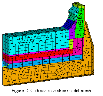
The 3D cathode side slice model provides an efficient way to compute the average cathode shell heat losses and the cathode lining drop. The model takes advantage of the natural longitudinal repetitive symmetry of the individual cathode lining blocks and shell cradle assembly. Hence, the model is half a cradle spacing thick (see Figure 2).

The best approach is to represent the shell walls, cover plate, stiffeners and cradles (if they are welded to the shell), using 2D plate elements. Since the shell steel mechanical structure also plays the role of cooling fins, it is important not to neglect them if one wants to be able to compare the measured shell temperature against the model results. Yet, it is the author experience that the


predicted global cathode shell heat dissipation will not be significantly affected by the addition of the structural elements of the shell. The reason being that the thermal resistance of the external air film is small compared to the thermal resistance of the global lining.

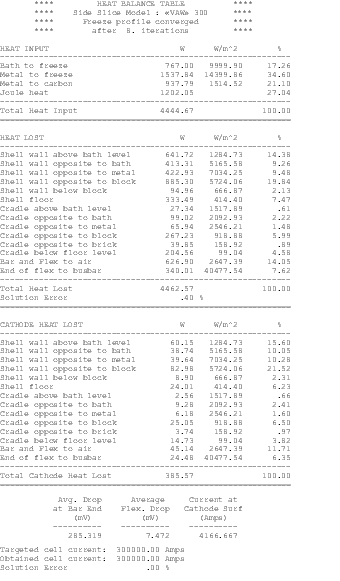
For the cathode model, the user must specify the cell operating temperature and the corresponding cell superheat. The model will compute the cathode shell heat losses. The model will also compute the ledge profile that corresponds to the assumed cell superheat for a given side wall design and given heat transfer coefficients at the ledge/metal and ledge/bath interfaces (see Table 2).

Table 2: Cathode slice model heat balance table

It is important to notice that to extrapolate from the cathode side slice model heat losses to the total cathode shell heat losses, the user must provide a multiplication factor that accounts for the end walls heat dissipation. This factor is of course proportional to the width to length ratio of the shell but is not a simple geometric factor, there are no collector bars in the end walls and often the end lining design differs from the one at the sides.

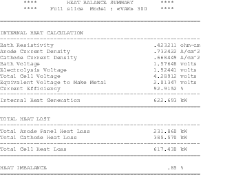
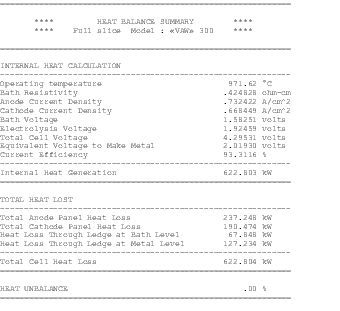
By having solved both the anode and the cathode models, it is possible to add up the results and compare the total with the cell internal heat. This last calculation can be done independently, but can also be performed within ANSYS® by an APDL macro created for that purpose (see Table 3). The advantages and disadvantages of the 3D cathode slice model are the same as those of the half anode model.

Table 3: Cell heat imbalance calculation

3D thermo-electric cell slice model

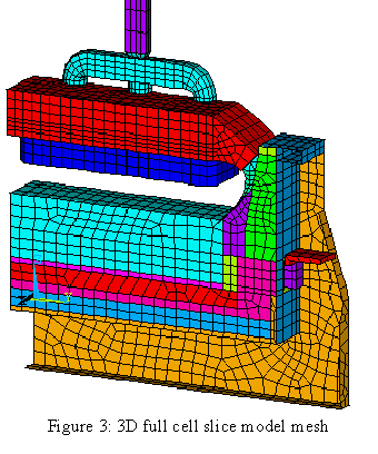
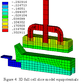
Once available, it is easy to merge the half anode model to the cathode slice model, since they must by definition share the same cutting plane boundary, to form a full cell slice model. Some nodes simply need to be moved and merged to ensure that the two parts are truly connected. The ANSYS® «ceintf» command can alternatively be used to connect the two parts without changing the mesh. Of course, the two models do not typically share the same thickness but this does


not prevent them to be glued together. Nor do they share the same current, but this is not an issue since the electrical part of both models will remain disconnected (see Figures 3 and 4).

The connection of both models into a global slice model only improved the model accuracy marginally by removing the «infamous» adiabatic

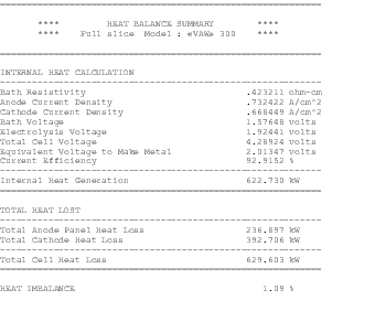
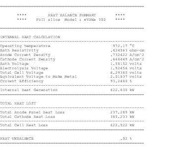
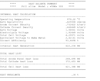
cutting plane. The heat balance macros of the anode and cathode parts of the model can still be used to compute the model heat balance. In addition, the summary result table can now be produced automatically without direct involvement of the user since all the required data are now available (see Table 4).

Table 4: Cell heat imbalance calculation

If we compare Tables 3 and 4, we can see that:

  • the global results are the same within 2
  • the global heat losses have increased

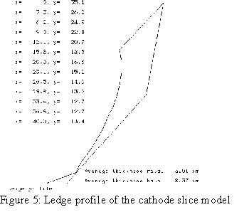
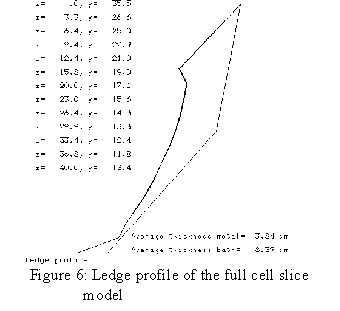
The converged ledge profile is also influenced slightly by the addition to the anode part as we can see by comparing Figures 5 and 6.


The cost of this improvement shows up in the time required to solve the global cell slice model compared to solving each part independently:

Table 5: Computer time comparison

Type of modelCPU time(sec) Elapsed time(sec)
Half anode 371 400
Cathode side slice 364 463
Global cell slice 1579 1809

The quoted times have been obtained on a Pentium II 266 MHz processor with 128 meg of RAM. Although the author will continue to recommend to keep the option to run the anode part independently from the cathode part for convenience, he must admit that the speed of today´s computer make you wonder if it is still worth to sacrifice 2% accuracy in the model results in order to gain some CPU time!

Now that the global cell imbalance can be computed as part of the model solution, there is no reason why the model could not find automatically the steady state cell operating temperature the same way the «classic» 2D model used to do it. This can be achieved without spending too much

extra CPU time by merging the ledge profile convergence loop with the new operating temperature convergence loop.

Yet, for this numerical scheme to be effective, one need a good initial guess of what will be the steady state operating temperature after having solved the model with the initial assumed profile and assumed operating temperature. To achieve this, the author wrote an ANSYS® macro that automatically computes the parameters of the 1D thermal model he have developed to perform dynamic analysis[1]. The 1D thermal model can then be automatically used to estimate the steady state temperature (see Table 6). Using this very good initial guess, it is possible to converge both the ledge profile and the operating temperature of the global cell slice model efficiently without increasing too much the required CPU time.

Table 6: 1D model cell temperature prediction

The converged results are presented in Table 7. As for the required computer time, it increased to 1983 sec. CPU and 2306 sec. elapsed which is around 25% higher than the previous solution time. The advantage of this model is obviously that it behaves like the «classic» 2D model. It is also slightly more accurate than the separated half anode and cathode slice models; its only disadvantage being the extra CPU time required per run.


Table 7: 3D full cell slice converged operating temperature

3D cathode corner/quarter model

3D cathode corner models are required when it is time to address the detailed lining design of end walls and corners of the cell. One key feature of the cathode corner model is its unique ability to help design the cell corner lining in order to tailor the ledge profile there. This is very important since it is well known that a strong horizontal current in the metal pad at cell corners can promote cell MHD instabilities[13,14]. Once the ledge profile has been converged it is possible to compute the current density in the metal pad[15] by adding the bath and metal to the model.

Having a quarter cathode model available is also quite useful to compute the exact value of the heat loss multiplication factor for the end walls as reported in [9]. Using an assumed value for that factor is obviously the single most important source of inaccuracy for any side slice model. Having a quarter model available is a big asset for a retrofit design team because:

  • it greatly improves the accuracy of the heat loss predictions of the thermo-electric model
  • it provides accurate current density input for the MHD model
  • it also provides input for the shell mechanical model since the complete thermal load applied to the shell structure is computed as part of the solution.

The obvious disadvantages are both the time required to build the model and the computer resources required to solve it. The quarter cell model presented in [9] took 23 CPU hours to solve on an SGI 4D/35 workstation while the cathode side slice model took only 43 min. Thus, the solution of the cathode quarter model required 32 times more CPU time than the cathode side slice model in that case. Since the Pentium II 266 MHz computer is about 6 times faster than the SGI 4D/35 workstation, the time required to solve the quarter model today will now be under 4 hours of CPU time.

3D full cell corner/quarter model

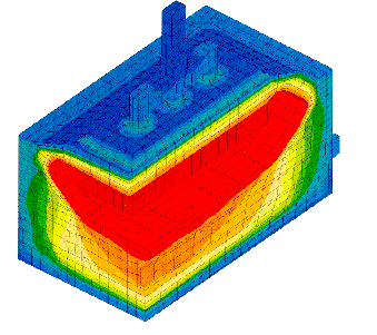
Considering the continuous increase of computer speed, one can expect that this new type of model, already used by Alusuisse[13] and VAW[12] (see Figure 7), could become the next standard in the years to come. Because it avoids both the cutting plane and the estimation of the end wall heat losses, it offers the highest potential for model results accuracy.

Figure 7 : VAW´s full cell corner model isotherms [12]


In the past, one disadvantage would have been the requirement to have a continuous mesh between the anode and the cathode parts. This would have been a problem because the anode repetitive unit width is usually different from the cathode repetitive unit width. For that reason, creating a continuous mesh at the interface between both parts of the model is a tremendous meshing challenge. Fortunately, ANSYS® now provides the command «ceintf» that takes care automatically of tying dissimilar meshed regions together. This disadvantage has therefore been eliminated.

The main disadvantage is the amount of computer resources required. Although the author has not yet tried to run that type of model, he would estimate it will required around 20 hours of CPU time on the Pentium II 266 MHz computer to solve the 3D full cell quarter thermo-electric version of his demonstration model (results will be available at the conference).

Improved 2D thermo-electric cell slice model

As the author said previously, his first assignment as a researcher in 1984-85 was to develop a new generation of 3D thermo-electric models to replace a 2D thermal «in-house» model. Because of the tremendous advantages of using 3D models over 2D models, he did not believe that 2D models had any place left in the cell designer´s tool kit. Two points made him reconsidered his position:

  • first, 2D models are still being used today despite of their obvious limitations[16,17]
  • second, the author has personally successfully developed a 1D thermal model to reproduce dynamic cell behavior[18] and to give fast answer to «what if» questions in brainstorming sessions[1], so a 2D model should do even better

Hence, there must be still a niche for a fast but yet still relatively accurate 2D thermo-electric model. The improved 2D thermo-electric model version the author has developed addresses the limitations

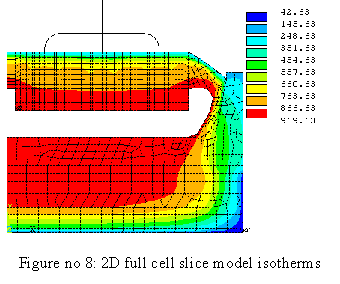
of having to represent anode studs and collector bars behavior in a 2D geometry model by representing them by using beam elements (see Figure 8).

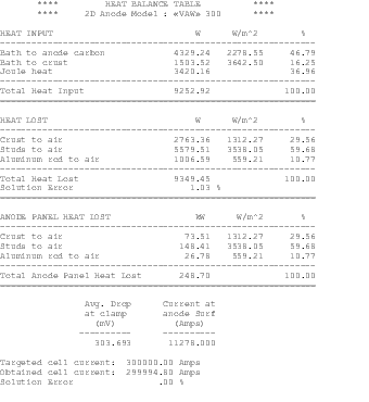
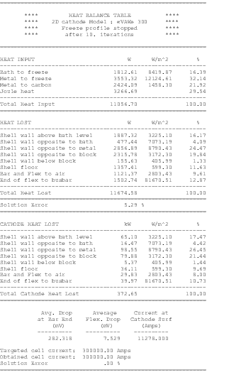
With this approach, once the cast iron/contact resistance interface elements that link the 2D carbon elements with the 1D steel elements have been calibrated to reproduce the 3D model results; the 2D cell slice model results are very similar to the 3D cell slice model results (see Table 8 to 10).

Table 8: 2D full cell model anode section heat balance table


Table 9: 2D full cell model cathode section heat balance table

Table 10: 2D full cell slice converged operating temperature

The disadvantage of this approach is obviously in the very imprecise representation of the effect of the contact resistance. It would be very tricky to use this model alone to study the effect of using different anode stud hole geometries or to study the impact of different designs of insulation around collector bars. But it obviously offers a big accuracy improvement over the «classic» 2D model representation.

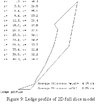
Its main advantage obviously resides in the greatly reduced time required to build and solve it compared to a 3D model. As a matter of fact, it took only 297 sec. CPU and 406 sec. elapsed for the Pentium II processor to solve this model including the convergence of the ledge profile and the steady state operating temperature (see Figure 9). Therefore, we gain a factor of 6.67 in speed over the 3D full cell slice model, which is not negligible for someone planning to do detailed dynamic thermal analyses!

Conclusions

In their 1985 TMS paper, W. Schmidt-Hatting and al. indicated that «1D, 2D and 3D models have each their advantages and limitations». This statement is still true today even if the cell designer´s tool kit of models has been greatly enhanced since that time. I guess the single most important difference is the fact that the complete tool kit is now a mature product commercially available to the whole industry.


References

  1. M. Dupuis, «Process Simulation», TMS Course on Industrial Aluminum Electrolysis, (1997).

  2. J.N. Bruggeman and D.J. Danka, «Two-Dimensional Thermal Modelling of the Hall-Héroult Cell», Light Metals, (1990), 203-209.

  3. W. Schmidt-Hatting and al., «Heat Losses of Different Pots», Light Metals, (1985), 609-624.

  4. H. Pfundt, D. Vogelsang and U. Gerling, «Calculation of the Crust Profile in Aluminium Reduction Cells by Thermal Computer Modelling», Light Metals, (1989), 371-377.

  5. M. Dupuis and V. Potocnik, «Comportement thermo-électrique d´une anode: étude théorique et expérimentale» (Report AR-86/0018 Centre de recherche et de développement Arvida, 1986).

  6. M. Dupuis, «Modèle tri-dimensionnel de simulation du comportement thermo-électrique d´une cathode» (Report AR-87/0004 Centre de recherche et de développement Arvida, 1987).

  7. M. Dupuis and I. Tabsh, «Thermo-electric Coupled Field Analysis of Aluminum Reduction Cells using the ANSYS® Parametric Design Language», Proceeding of the ANSYS® Fifth International Conference, volume 3, 17.80-17.92, (1991).

  8. M. Dupuis and I. Tabsh, «Thermo-electric Analysis of Aluminum Reduction Cells», Proceeding of the 31st. Conference on Light Metal, CIM, (1992), 55-62.

  9. M. Dupuis and I. Tabsh, «Thermo-electric Analysis of the Grande-Baie Aluminum reduction cell», Light Metals, (1994), 339-342.

  10. D. Vogelsang and al., «Retrofit of Söderberg Smelter at Alusaf Bayside Plant Part 1 – Conceptual Design and Engineering», Light Metals, (1996), 327-333.

  11. D. Vogelsang and al., «From 110 to 175 kA: Retrofit of VAW Rheinwerk Part I: Modernization Concept», Light Metals, (1997), 233-238.

  12. VAW Aluminium - Technologie GmbH pamphlet, «Know-how and Expertise in Aluminium» (1995).

  13. J.P. Antille and al., «Effects of Current Increase of Aluminium Reduction Cells», Light Metals, (1995), 315-321.

  14. P.A. Davidson and R.I. Lindsay, «A New Model of Interfacial Waves in Aluminium Reduction Cells», Light Metals, (1997), 437-442.

  15. M. Dupuis and I. Tabsh, «Thermo-electro-magnetic Modelling of a Hall-Héroult Cell», Proceeding of the ANSYS® Sixth International Conference, volume 4, 9.3-9.13, (1994).

  16. A. Vallés, V. Lenis, «Prediction of Ledge Profile in Hall-Héroult Cells», Light Metals, (1995), 309-313.

  17. M.M. Ali and A.A. Mostafa, «Improvement of the Aluminum Cell Lining Behavior by Using SiC», Light Metals, (1997), 273-277.

  18. I. Tabsh, M. Dupuis and A. Gomes, «Process Simulation of Aluminum Reduction Cells», Light Metals, (1996), 451-457.