THERMO-ELECTRIC ANALYSIS OF ALUMINUM REDUCTION CELLS
Marc Dupuis, PhD.
Alcan International Limited
Arvida Research and Development Centre
1955 Mellon Blvd., Jonquière, Québec, Canada G7S 4K8
Telephone (418) 699-3237, Fax (418) 699-6378

Imad Tabsh
COMPUSIM Inc.
1003-D 55 Avenue N.E.
Calgary, Alberta, Canada T2E 6W1
Telephone (403) 295-2912, Fax (403) 274-6908
ABSTRACT
The cathode of an aluminum reduction cell consists of a steel structure lined with bricks and other insulation materials. An efficient cell cathode design has an optimum heat balance that minimizes energy consumption and cell failure. The design relies on the solidification of the electrolyte against the side of the cathode to provide a "freeze" layer which protects the lining against erosion.
The thermo-electric analysis capabilities of the commercially available finite element code ANSYS® were used to model the freeze profile of reduction cells. The geometry of the structure was defined parametrically to allow for quick evaluation of design alternatives. For a specific cell and cathode design, at a given level of heat input, the freeze profile was automatically adjusted to arrive at the converged profile.
INTRODUCTION
The Alcan group of companies is an international industrial group engaged in all aspects of the world aluminum business. It is one of the lowest-cost producers of primary aluminum in the world. A corporate mission statement sets Alcan's goals "to be a global, customer-oriented and environmentally responsible enterprise committed to excellence and lowest-cost in its chosen aluminum and related business".
It is one of the mandates of Alcan International Limited to develop mathematical models of Alcan's major aluminum production and fabrication processes. Advanced mathematical models are viewed as essential tools to help Alcan meet the environmental, technical and economic challenges that lie ahead.
This paper describes the use of the commercially available finite element program ANSYS® to model the freeze profile in a Hall-Héroult aluminum reduction cell. The ANSYS®. parametric design language (APDL) is extensively used to idealize the structure and facilitate the evaluation of several design alternatives.
The Aluminum Reduction Process
Electrolytic cells, commonly known as pots, are used to reduce alumina to aluminum metal. A typical cell consists of a steel structure protected by brick linings in which a molten electrolyte is maintained at high temperature (~ 1000° C). Rectangular carbon anodes suspended in the electrolyte act as positive electrodes while a layer of molten aluminum below the electrolyte acts as a negative electrode (cathode). Alumina, which is dissolved in the electrolyte, is reduced to aluminum when the electric current flows through the electrolyte from the anode to the cathode. The aluminum settles to the bottom of the electrolyte and is tapped regularly. Carbon dioxide is formed at the anode.
Optimum Cell Design
Considerable electrical energy, between 13 to 16 kilowatt-hour per kilogram of aluminum, is expended during the process. Maintaining the proper heat balance in the cell is critical for minimizing energy consumption and promoting ease of cell operation. The design of the cell should be such that it maintains exactly the correct bath temperature, and the heat flow should be sufficient to maintain a layer of frozen electrolyte (freeze) over the side wall for protection. Insufficient bottom insulation may lead to excessive frozen bath covering the cathode, which will interfere with the normal current flow pattern leading among other things to higher cell voltage.
On the other hand, too much insulation will prevent the freezing of the bath on some areas of the side wall, and that ultimately may result in erosion and early side-lining failure. The formation of freeze on the pot walls serves as a protective layer against erosion of the side wall lining. This leads to a longer life for the pot and a reduction in spent pot lining. The latter represents the largest volume of solid waste generated by the aluminum smelting process.
Hence, optimization of the cell design has the benefit of reducing operating costs and the environmental impact of the process.
FINITE ELEMENT MODELING
The complex geometry and generation heat within the anode, cathode and current conductors makes a combined calculation of the heat and current flow by finite element methods desirable. A thermo-electric model permits the calculation of the location of isotherms in the cathode, the freeze profile and the heat dissipated from the process. Various combinations of lining materials could be investigated to determine the optimum design that produces the best side wall protection and the minimum power consumption.
Model Description
A finite element model of a typical cell was developed using ANSYS®. The model was designed to meet several requirements including:
| . | Perform a steady state, coupled field thermo-electric analysis. Joule heat resulting from the electric current flowing in the cell along with heat flux calculated from a fixed liquid temperature constitute the heat input. Heat is lost on the outside surface of the pot shell through convection and radiation. |
| . | Represent non-linear behavior. Material properties are a cubic function of temperature; convective surface film coefficients are also temperature dependent; and radiation effects have a fourth order variation with temperature. All these non-linearities were accounted for in the model. |
| . | The ability to calculate the total heat balance with a break down by various areas of the structure to ensure easy comparison with measurements. |
| . | Variable model size. Three levels of problem complexity were allowed for in the input scheme: a slice model representing half a cathode block at the center of the pot; a corner model representing the end wall with one or two cathode blocks; and a full quarter of the pot. Each model required more computing resources. Using smaller models provides a quick method of evaluating design alternatives. |
The ANSYS® parametric design language (APDL) was used to define the non?linear material properties in the model. In addition, effective surface film coefficients were calculated in ANSYS® to represent the combined convection and radiation effects on external surfaces of the model. Details of the ANSYS® implementation of the above were discussed in a paper presented at the ANSYS® Fifth International Conference in May 1991 [1].
Parametric Looping Logic
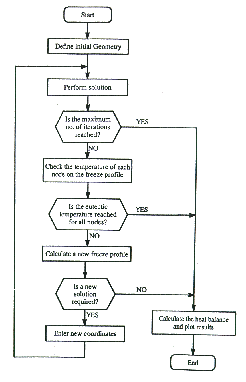
The calculation of the final freeze profile is an iterative procedure due to the non-linear aspects of the problem. The shape of the freeze profile is dependent on the surface temperature, which in turn is dependent on the geometry of the model. Figure (1) shows the looping logic implemented in the model. The objective is to change the assumed geometry of the freeze profile such that all the nodes on the surface are within a prescribed tolerance of the eutectic temperature. The following steps are performed:
| . | Calculate the freeze profile temperature for a given geometry. |
| . | Check whether the temperature of all nodes on the freeze is within a specified tolerance relative to the eutectic temperature. |

Figure 1 - Flowchart of freeze profile adjustment loop
| . | If required, calculate a new location for the freeze profile nodes by linear interpolation / extrapolation. Calculate the thickness of freeze that would bring the surface temperature to the eutectic temperature. |
| . | Move nodes only if their new location is further away from their current position by more than a prescribed tolerance. |
| . | If any nodes require adjustment then create a new input file with the new coordinates. |
The above steps were repeated until (1) all temperatures on the freeze surface were within the eutectic temperature range; or (2) all nodes did not move by more than the prescribed tolerance; or (3) a preset number of iteration loops was reached. Note that within each solution step several iterations were performed by the solver to satisfy the non-linear material behavior.
Case Historv
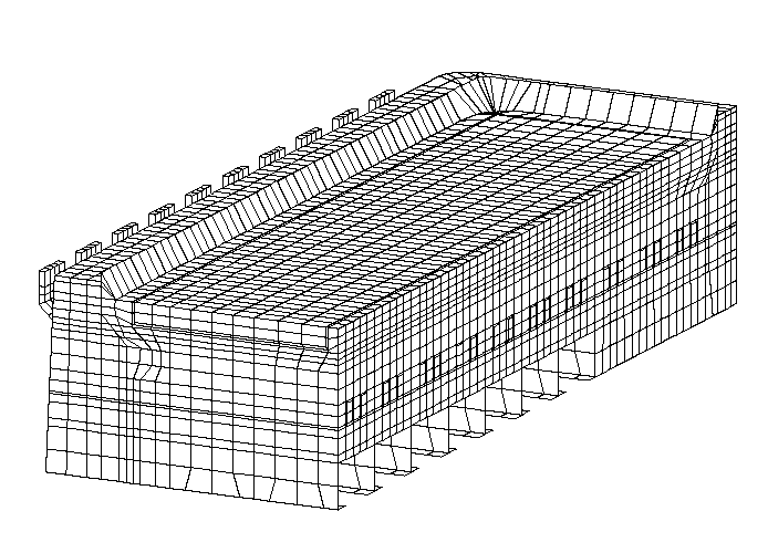
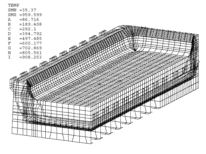
The finite element model described above was successfully developed and used to design a new cell. figure (2) shows a mesh plot of the final quarter model of the design. The model consists of 19054 nodes with 28269 degrees of freedom. 18644 elements were used to idealize the structure. It took 15 iterations of the freeze loop to converge to the final solution. The temperature of the freeze profile was calculated to within ½° of the eutectic temperature. To achieve such an accuracy it was necessary to define a 0.1 mm tolerance on the freeze thickness. The model processing time on a 4D-35 Silicon Graphics Personal his with 32 MBytes of RAM running Version 4.4A of ANSYS®, was almost 17 CPU hours with an elapse time of more than 22 hours. Figure (3) shows a temperature contour plot of the converged solution.
CONCLUSIONS
The finite element method provides an excellent tool for the design of an optimum aluminum reduction cell. The commercial program ANSYS® was successfully used to develop a general purpose tool for designing cells. The parametric design language capabilities of the program were especially useful in the following areas:
| . | The slice/corner/quarter model flexibility reduced considerably the elapse time for designing a new pot. Several design variations were eliminated with the slice model while the quarter model was used to validate the final design. |
| . | The ANSYS® environment provides portability between computer platforms. The model was developed and run on a Silicon Graphics Personal Iris (4D-35). It was successfully run without any changes on a CRAY XMP-24 and on an HP 720 workstation. |
| . | The parametric setup of the model allowed for easy and quick design changes. Material as well as geometry modifications were performed by simply changing the value of a parameter. |
| . | Results tables and plots were automatically created within the program. They were extracted from the output files and included in reports with minimum effort. |

Figure 2 - Mesh plot of a quarter model of a typical cell

Figure 3 - Temperature contour plot of the converged solution
ACKNOWLEDGMENTS
The authors would like to thank H.G. Engineering in Toronto, Ontario for their ANSYS®. support and their help in the initial development of the slice model. H.G. Engineering is the ANSYS®. Support Distributor for Eastern Canada.
REFERENCES