Marc Dupuis
GéniSim
3111 Alger St.
Jonquière, Québec, Canada G7S 2M9
http://www.genisim.com
e-mail:
|
Abstract Ten years ago, a full 3D transient thermo-electric F.E. model was developed to study the thermal gradient generated in the lining during coke preheat [1,2]. The model development and applications turned out to be very costly because the model had to be run on expensive supercomputers. Nowadays, this type of model can easily be run on inexpensive Pentium III computers. This paper presents a typical model application for a modern prebaked cell running at 300 kA. Introduction The coke resistor preheat is the current technique used by the industry to bring into operation modern high amperage cells. Yet, as raised by Dunn et al [3], little published information is available on how to actually design a coke preheat. It would be nice to be able to design a coke preheat that minimizes the preheat duration without producing excessive harmful thermal gradients in the cathode lining. To do so, there are many design parameters that can be optimized:
|
Thermo-electric F.E. model It seems obvious today that the best way to proceed to optimize the coke preheat design parameters should be to use a mathematical model. The characteristics of the model to be used are dictated by some basic requirements:
Practically, this means building and solving in transient mode a fairly big model. Yet, the main purpose of this paper is to demonstrate that this type of model has now become quite affordable as opposed to when it was first developed 10 years ago [1,2]. |
|
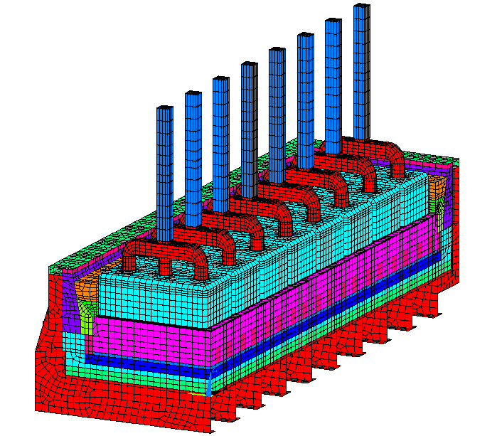
Step 1: Model construction The first challenge is to build the 3D finite element mesh of the cell in coke preheat configuration (see Figure 1). Fortunately, this is quite straightforward to do if a 3D finite element mesh of the same cell in standard operation configuration already exists (see Figure 2). As discussed in previous publications [4,5], building a full cell quarter model of the cell in normal operation configuration will greatly contribute to increase the accuracy of the heat balance model predictions. In turn, this will reduce the risk of designing a prototype that will not operate as predicted. To convert a 3D full cell quarter mesh from a standard operation configuration into a coke preheat configuration, one simply has to:
The issue of the mesh transition between the anode panel part and the cathode panel part can easily be taken care of in the new coke bed elements. The mesh does not need to be continuous there as the accuracy of the thermal gradient prediction in the coke bed itself is not important. Step 2: Model solution The second challenge is to solve a fairly big 3D model in transient mode. The amount of computer CPU time, RAM memory and disk space required to solve such a big model in transient mode used to translate into a fairly expensive model application cost. As an example, the coke preheat model presented in [1,2] had to be run either on a very expensive supercomputer or a still fairly expensive high end workstation. In addition to the cost of buying or renting time for the hardware, the cost of renting an ANSYS« license on those platforms was also quite expensive. |
In contrast, the solution of an even bigger coke preheat model (95,777 elements) for a quite similar 30 hours preheat can now easily be solved on a US $ 5,000 Pentium III computer (single 800 MHz processor with 384 MB of RAM and 2 SCSI disks for a total of 27 GB of disk space). Solving the 30 hours preheat using 36 load steps required 171.5 CPU hours (see final solution in Figure 3). As far as disk space is concerned, the results file containing all the 36 load steps results required 3.711 GB ! This is still a fairly long time to wait for a solution and this clearly indicates that faster computers are still required to be able to run this type of model with an acceptable turn around time. Yet, it is important to point out that the cost of that CPU time has now become negligible. So has the cost of the ANSYS« license as the above solution was obtained using a permanent ANSYS« 5.3 THERMAL UNLIMITED license paid US $ 10,000 in 1996. Step 3: Model validation Except for demonstration models like the one presented here, model validation is the next step to perform. Unfortunately, performing this step still requires an extensive and expansive instrumentation package in order to be able to gather the precious validation data. On the other hand, gathering such data is required anyway to validate the selected coke preheat practice even if a model is not involved in the exercise [3]. For more information on gathering validation data in order to validate a coke preheat model, it could be useful to note that the validation data presented in reference [1,2] were obtained using the instrumentation package described in reference [6]. The model is typically calibrated to reproduce the measured temperature evolution curves by adjusting hard to assess properties like the evolution of the coke bed resistivity with time/temperature by trial and error. This obviously requires a fast turn around time which is not the case if 171.5 CPU hours is required per run! This is why, it could be useful to consider to perform the model calibration runs using only a subset of the full model like a full cell side slice model (see Figure 4). |
Figure 1: Quarter mesh in coke preheat configuration
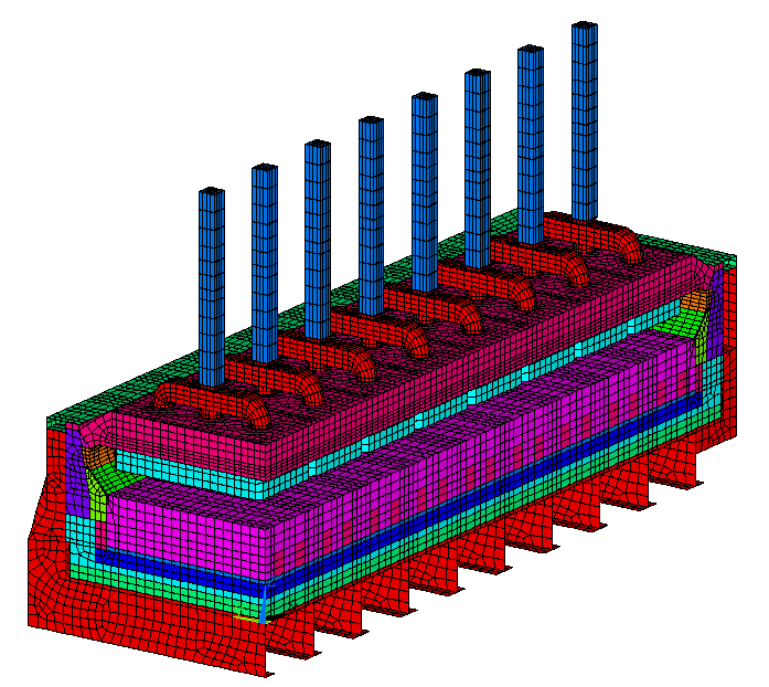
Figure 2: Quarter mesh in normal operation configuration
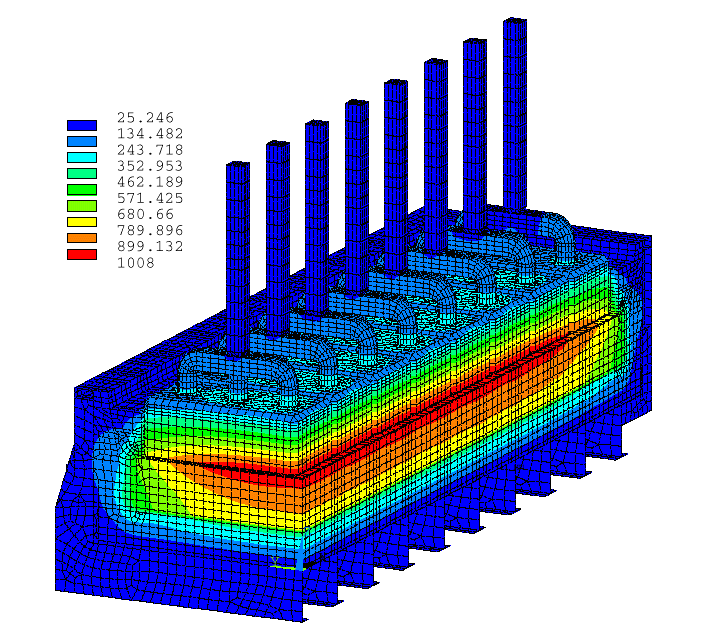
Figure 3: Isotherms after 30 hours preheat
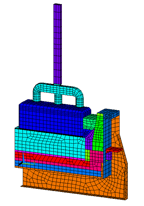
Figure 4: Side slice mesh in coke preheat configuration
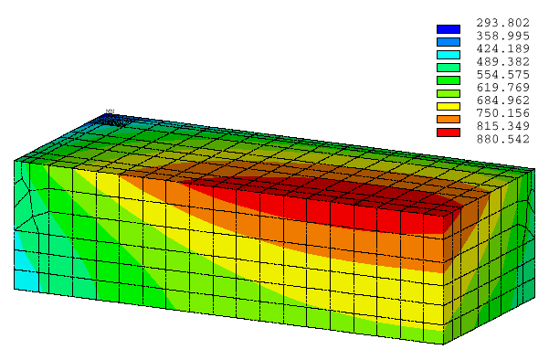
Figure 5: First block thermal gradient (isotherms) after 30 hours preheat
|
Step 4: Model application Once the model has been validated in order to well reproduce the measured thermal gradient for the current coke preheat practice, the model can be used to investigate the impact of changing design parameters like the shape of the coke bed on the model predicted thermal gradient [1]. Typically, simply looking at the obtained thermal gradient in critical section of the lining as in the first cathode block per example (see Figure 5) is useful but not sufficient. The next step would be to compute the thermal stresses generated in the lining using the thermal gradient as input in a mechanical model in order to see if the level of stress exceeds the material limit [2]. Obviously, solving this mechanical model requires even more CPU time and also the usage of a more expensive ANSYS« MECHANICAL license (license that was not available during the preparation of this paper). Conclusions It was demonstrated that it is now possible to solve a full 3D transient thermo-electric coke preheat model on an inexpensive Pentium III computer. It was also explained why the marginal cost of developing a coke preheat model is very small when a full 3D thermo-electric model in standard operation configuration is already available. As for the potential benefits of using such a coke preheat model to optimize the design of the coke preheat practices, any smelter experimenting a significant rate of early lining failure would easily identify them ! |
References
|