5) have a small impact on the overall displacements along the
width of the cell, but have a large impact on the stress-strain
behaviour of the lining. This aspect will be covered later on.
The deformed shape of the lining at the end of the preheating can
provide a strong indication on the formation of gaps where bath
could potentially leak. For example, Figure 9 shows the final
deformed shape for a 24 hours preheating to 955ºC
(corresponding to the temperature distribution in Figure 7a), with
displacements amplified by a factor of 10. As expected, the
cathode blocks are bending up and compress the ramming paste.
A gap opens between the ramming paste and the pier as the
cathode block pushes up the paste (Figure 9, A). The thermally
induced deformation of the shell also opens up a gap between the
side block and the sidewall near the deckplate (Figure 9, B).
(Figure 5) on the response of the cathode block was investigated.
Two extreme cases were simulated: full symmetry and free to
move. This corresponds respectively to an infinitely rigid shell,
and to a perfect expansion joint along the length of the pot.
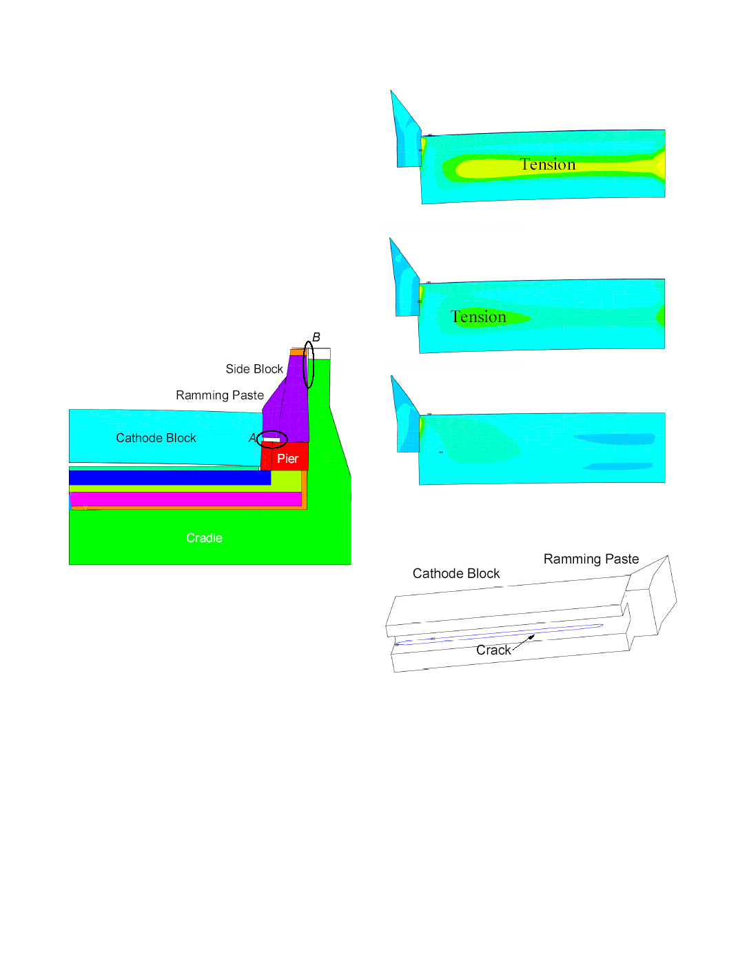
Faster preheating rates mean larger thermal gradients in the
cathode blocks, which leads to tensile stresses as shown in Figure
10. For the studied cases where the lining surface on plane P3 is
free to move, these stresses were not sufficient to crack the block.
found that for all our studied cases, the cathode block is
permanently deformed and cracks occur in the collector bar slot.
A typical cracking pattern is shown in Figure 11. When the lining
surface on plane P3 is free to move, no such crack develops.
used for the thermo-electric design of a cell [14]. Given the
significant difference of behaviour of the cathode block with the
change in boundary conditions on plane P3, it is clear that a slice
model cannot be trusted to accurately predict cathode cracking
during preheating unless the shell provided no confinement along
the length of the pot, or otherwise if it was infinitely rigid. As this
is rarely the case in practice, at least a quarter cell should
therefore be modeled. Obviously, this is also required to study the
corner of the cell.