pressure-dependent) can be used at an interface, for example to
emulate the effect of a mortar joint. Thermal conductance values
were estimated from [11]. The interfaces are assumed to be non-
cohesive, i.e. they cannot sustain a tensile stress.
The cradles are welded to the shell, and the steel plate thicknesses
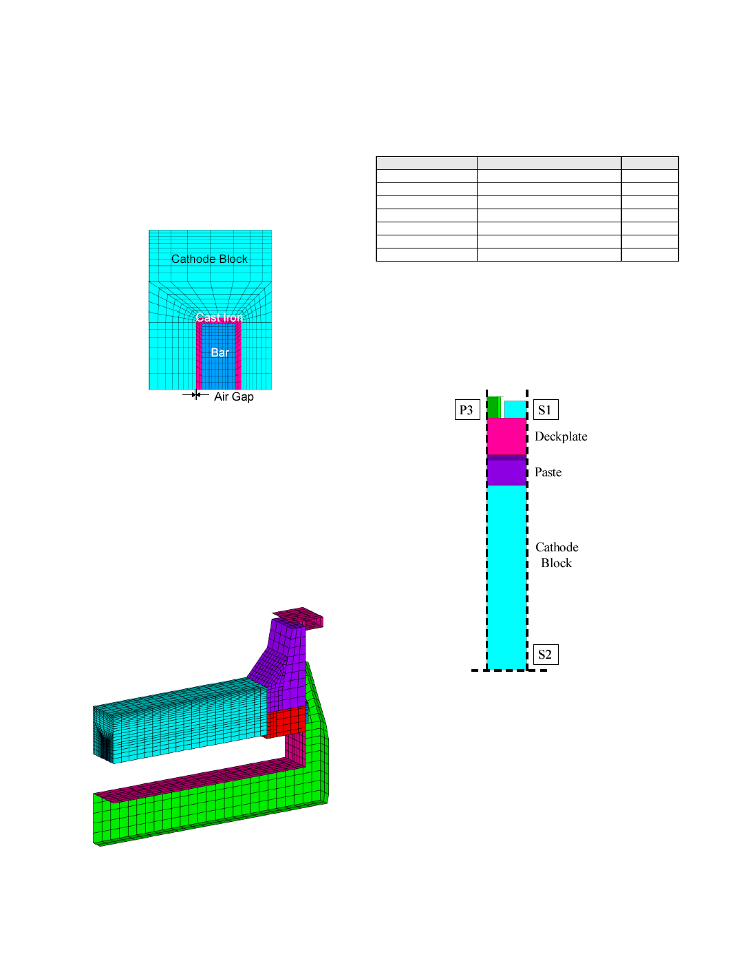
were estimated from experience [12]. The collector bar is rodded
with cast iron, and a simple geometry was assumed, as shown in
Figure 3. At ambient temperature, an air gap is present between
cast iron and carbon, and as the assembly heats up, thermal
expansion of the parts eliminates this air gap.
bending stiffness because in this design there is a layer of
insulating refractory fibre wool that will absorb its thermal
expansion in the horizontal plane. Therefore, the brick lining
under the cathode does not contribute significantly to the
mechanical response of the cell during preheating and is
accordingly not solved in the mechanical problem. Conceptually,
the cathode block and the pier are assumed to rest on springs of
equivalent stiffness to the underlying brick lining. This is
implemented in the finite element model by using contact
mechanics to connect the shell floor to the bottom of the collector
bar and pier. The mechanical mesh is shown in Figure 4. Note that
the whole slice is solved for temperature (see Figure 1).
constitutive laws are summarized in Table 1.
be included to stabilize the problem, since the lining is mostly free
to move in the upward vertical direction.
The dashed lines in Figure 5 represent planes S1, S2 and P3 on
which symmetry conditions could be applied.
cradle, P3 is obviously a true symmetry plane as well. However,
the conditions for the lining on plane P3 are difficult to evaluate.
It reality, the confinement on this plane is the result of the
interaction between the lining and the shell along the length of the
pot. For this study, the two extreme cases were considered for the
lining on plane P3: symmetry conditions, and free to move.
The thermal boundary conditions for all external surfaces take
into account natural convection and grey body radiation, using
well-known semi-empirical correlations, and were taken from [9].
The surface of the ramming paste and the sidewall are insulated
by crushed bath. A convection coefficient of 1 W/m