brittle
with confinement, they are permanently deformed at only a
fraction of their peak stress, and they are significantly stronger in
compression than in tension. Concrete, dense bricks and carbon
[5] are all quasi-brittle materials.
compression, regardless of the confinement. Therefore, it is
unrealistic to assume a steel-like behaviour for the cell lining, as it
will not provide an adequate tool to predict cracking.
during preheating, it is still possible to undergo a local unloading.
For example the load would decrease in the region surrounding a
growing crack, or when a material experiences a contraction. For
instance, this is the case with ramming paste as it is baked.
mechanically-induced irreversible deformations in a material in
order to capture the potential opening of gaps in the lining and to
predict correctly the stresses.
the effect of sodium and the associated chemical reactions within
the refractory lining can be ignored.
and will undergo irreversible transformations of their
microstructure. This will affect their thermal and mechanical
behaviour. In general, these reactions also cause an irreversible
volume change.
should seal the lining while accommodating some of the cathode
blocks expansion. It is also difficult to characterize and to model.
It was reported that during baking, most pastes first expand and
then shrink. A plausible explanation is that the initial swelling is
caused by a build-up of reaction gases while the subsequent
shrinkage is due to the cokefaction of the binder phase [6,7].
order of magnitude during baking while its ductility decreases in
the same proportion. Its behaviour evolves from being almost
incompressible and plastic to that typical of quasi-brittle
materials.
a constant load, a phenomenon known as creep [6]. Some of this
additional deformation is recovered over time when the load is
removed, but the rest of it is permanent. Creep relaxes the stresses
in the material but also increases the risks of opening gaps, since
it increases the deformation for a given load.
join others. However, most interfaces cannot be assumed to be
completely cohesive. Joint behaviour has a profound effect on the
stiffness of the structure, and it is of paramount importance to
characterize this correctly for the accurate prediction of a possible
gap opening in the lining.
neglect cohesion altogether. This means that this interface cannot
sustain a tensile stress and that a gap will open under a tensile
loading.
For demonstration purposes, a realistic prebaked point-fed 300 kA
cell design inspired from a VAW publication [8] was used. The
thermo-electrical results, using ANSYS, are presented in [9] for
normal steady-state operation.
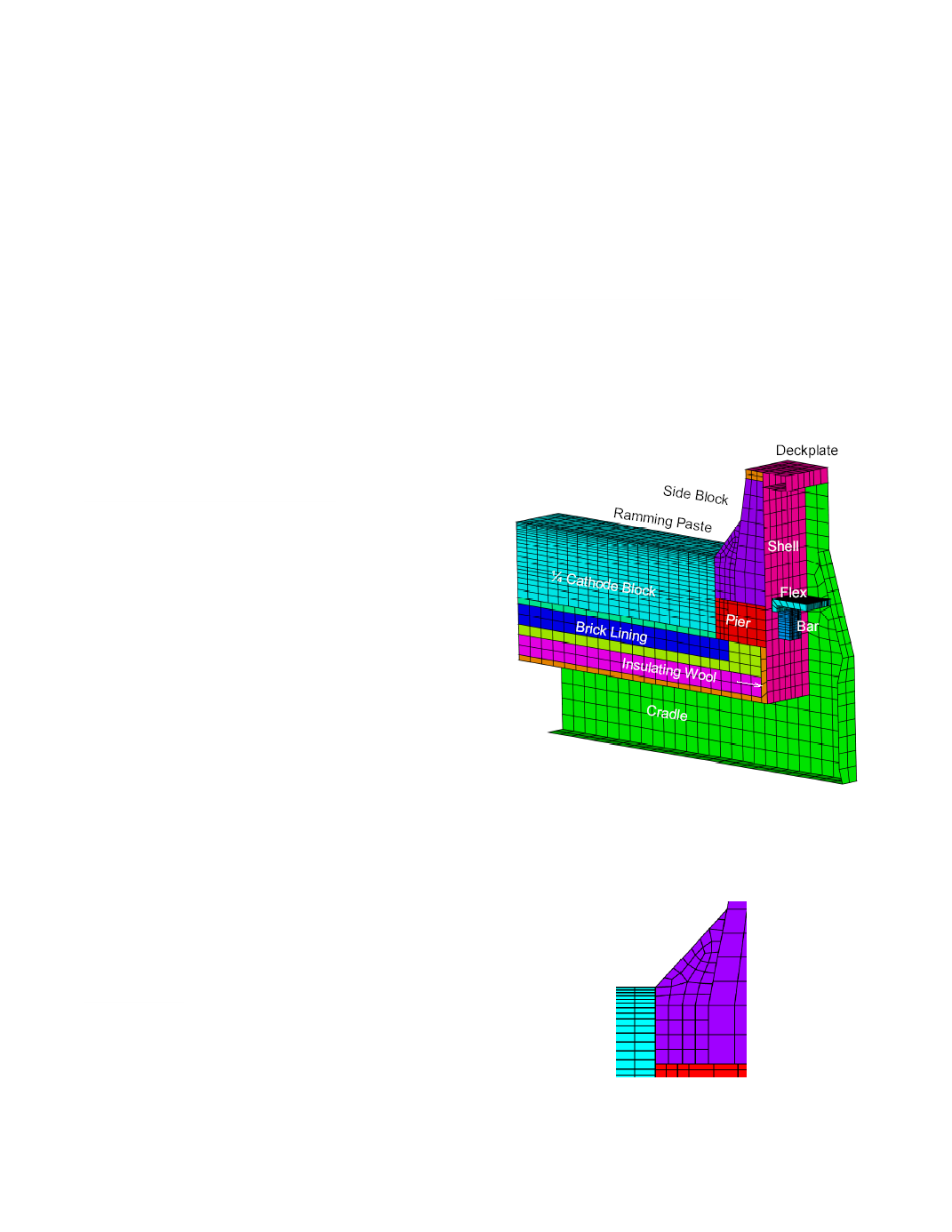
the finite element toolbox FESh++ [10] to illustrate the effect of
the heating rate at the center of the cell. The slice mesh represents
a quarter cathode and its corresponding lining, shell and cradle, as
shown in Figure 1. The shell and cradle are discretized using large
rotation shell elements while the lining is discretized using 3D
brick elements. The cathode blocks are glued together, as can be
seen from the absence of a small joint.
can be seen from the non-concordant mesh at the interfaces
between different parts (Figure 2).