ON THE IMPORTANCE OF FIELD VALIDATION IN THE USE OF
CELL THERMAL BALANCE MODELING TOOLS
Marc Dupuis1 and Richard Jeltsch 2
1 GéniSim Inc., 3111 Alger St., Jonquière, Québec, Canada G7S 2M9
marc.dupuis@genisim.com
2 Richard Jeltsch Consulting,
11407 N Kathy Dr, Spokane, WA 99218 USA
jeltsch@comcast.net
Keywords: Modeling, thermal balance, model validation, cell autopsy
Abstract
This cycle is required for two reasons, one is to measure the
Mathematical models have become essential for the design of
behavior of cell prototypes that are testing innovative design
modern, efficient high-amperage reduction cells, but the models
ideas, for example the replacement of carbon side blocks with SiC
are only one part of the cell design process. Since many of the
or collector bars with copper inserts.
inputs to a thermal balance model are difficult to evaluate, a
process for validation of the predictions of the model is essential.
The second reason is the collection of data to be used for model
validation. This is very important because models are only as
The validation process typically includes two sources of feedback:
good as the quality of the inputs used to set them up, hence the
from operational pots and from post-mortem examination.
famous expression: “garbage in, garbage out”.
Measurements of temperatures, heat fluxes and ledge shape must
The temperature dependent material properties used in models are
be made on the operating pots. In addition, prototype pots are
shut down for post-mortem examination (cell autopsy) which is
such critical model inputs. In models, those properties are set to
the only way to evaluate transformations of materials.
be temperature dependent but this image is misleading as it is not
the complete picture.
The transformation of materials during operation is one of the
For example, refractory brick manufacturers do provide
major reasons why model predictions do not match real operation.
temperature dependent thermal conductivity data obtained by
The risk of using unvalidated models to carry on design work is
testing their bricks at different operating temperatures.
highlighted through the presentation of a real example from the
past.
However, in a Hall-Héroult cell, the cathode lining is exposed to
Introduction
chemical degradation that will significantly affect its properties.
Those affected properties are the ones that need to be used as
As described in the introduction to the modeling section of
inputs in models and those properties are especially difficult to
Essential Reading in Light Metals Vol. 2 [1], modeling of Hall-
assess [4, 5].
Héroult cells went from essentially non-existing, to being very
expensive and mostly fruitless, to finally becoming a big success
Only data obtained from cell prototypes in steps 4 and 5 of the
story, finally becoming indispensable in the process of designing
cell development cycle can be used in order to get reliable
modern, efficient high-amperage cells [2]:
predictions from cell thermal balance models.
“Hall-Héroult cells are very challenging to model. This is true
Prototype cells heat balance measurement campaigns
now and it was especially true half a century ago. The aluminum
industry has invested huge resources in the development of
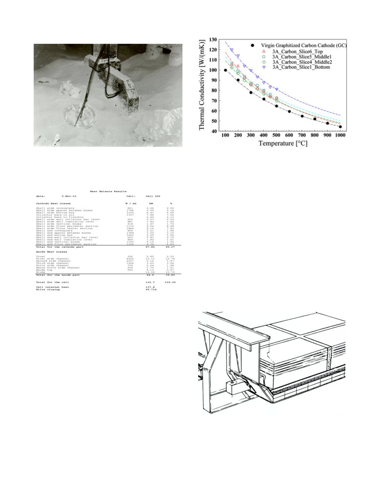
The first way to verify the accuracy of cell heat balance model
mathematical models especially to support its cell design
predictions is to directly compare them with data obtained from
activities. Today the use of mathematical models is considered
prototype cell heat balance measurement campaigns [6, 7].
indispensable to the successful design of efficient high current
cells”.
This technique consists of measuring the heat flux on enough
locations of the external surface of the cell to be able to calculate
In order to be successful, the design of high amperage cells must
the global heat loss of the cell such as the one presented in Table
be conducted using the “cell development cycle” method [3]. The
1.
method comprises several steps, from modeling to measurement
campaigns that must be used in repetitive cell design
Cell heat balance models will generate equivalent cell heat
improvement cycles:
balance predictions that can be compared at posteriori to the cell
heat balance measurements. Considering the accuracy of
1) Cell design through modeling
individual cell measurements of +/- 5% in the best cases, several
2) Cell engineering and prototype cells construction
such cell heat balance measurements are required to ensure that
3) Prototype cells operation
the model is calibrated using reliable data.
4) Prototype cells measurement campaigns
5) Prototype cells postmortem autopsy
Comparison of the global heat loss and the heat loss partition will
6) Model calibration and validation
tell if the model predictions were right or not but will not directly
tell what need to be adjusted if the predictions were not perfect.
Figure
2: Example of thermal conductivity of spent cathode
Figure 1: Measurement of the heat flux on the crust and the anode
blocks obtained from pot autopsy, Figure 12 in [5]
yoke using heat flux probes from Japan in the 70’s
The over insulated cathode example
Table I: Measured cell heat loss from
Hirakud HSS 55 kA cell, table II in [7]
Very often, technical papers and training courses discuss the
importance of respecting certain guidelines having in mind some
past mistakes and failures without actually discussing any of those
mistakes and failures.
In this paper, such a practical example from the recent past will be
presented in detail in order to clearly highlight the consequences
of using an unvalidated cell heat balance model to come up with a
cathode lining design.
This practical example is quite well covered in the literature [8, 9,
10]. It is the case of the over insulated Alcoa P155 cathode lining
as explicitly specified in [10]. Notice that the original Alcoa A697
lining design is essentially the same. The original lining design is
presented in Figure 3 taken from Figure 1 in [10]. There are 2
very thick layers of calcium silicate slabs just above the potshell
floor. Calcium silicate is a fairly good thermal insulator; typical
temperature dependent thermal conductivity of that material is
presented in Figure 4.
Prototype cells postmortem autopsy
The only way to directly obtain the required used material
properties required as inputs in models is to stop the prototype
cells, dig out samples and measure the properties of those samples
at a range of operating temperatures.
This is typically done in parallel with postmortem cell autopsies
which more typically are carried out to determine the mechanism
of failure of cells that tapped out or had to be stopped just before
it happened [8]. Yet, it is not uncommon to stop some prototype
cells for the purpose of obtaining the type of data presented in
Figure 2 for example. This is very costly, of course, illustrating
well the importance of using a properly validated model in order
to come up with an optimum cell design using a minimum of cell
development cycles.
Figure 3: Original lining design of the Alcoa P155 cell, Figure 1
in [10]
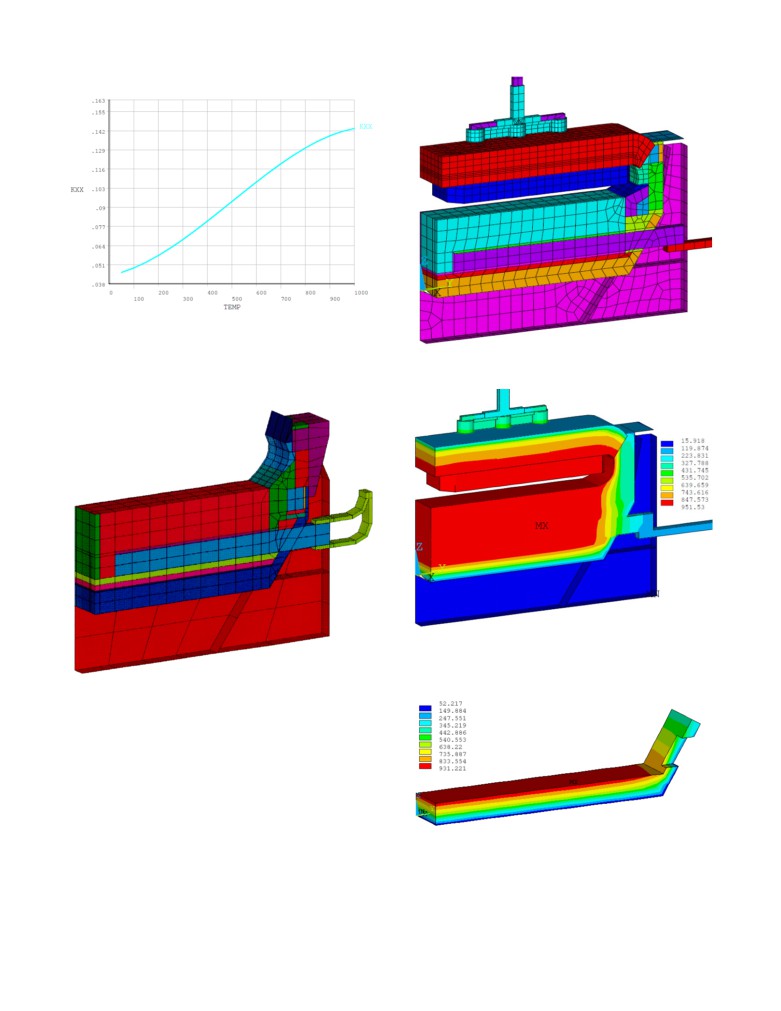
Figure 4: Temperature dependent thermal conductivity of new
calcium silicate material
In [10] several types of cathode models were presented; Figure 5
Figure 6: A697 full cell slice model mesh used in this study
shows the cathode side slice model. The navy blue material above
the potshell floor is the calcium silicate.
Figure 7: A697 full cell slice model temperature solution using
new calcium silicate property
Figure 5: P155 cathode side slice model mesh as developed in
1993, Figure 5 of [10]
That model is no longer available to the authors but a full cell
slice of the A697 developed by GeniSim and presented in Figure
6 is available instead. In that model, the calcium silicate is gold.
That A697 full cell slice model was run first using the new
calcium silicate temperature dependent thermal conductivity
presented in Figure
4. The obtained temperature solution is
presented in Figure 7. Notice that contrary to the cathode slice
model presented in [10], the full cell slice model presented in here
calculates first the cell internal heat from that anode-to-cathode
distance (ACD) specified by the user as input and converged in
Figure 8: Calcium silicate temperature solution using new calcium
parallel the cell superheat and the ledge thickness so that the
silicate property
presented converged solution is in thermal balance i.e., the cell
dissipates exactly the calculated cell internal heat.
The temperature solution of only the calcium silicate material is
presented in Figure 8, we can see that the top section is reaching
above 900 °C.
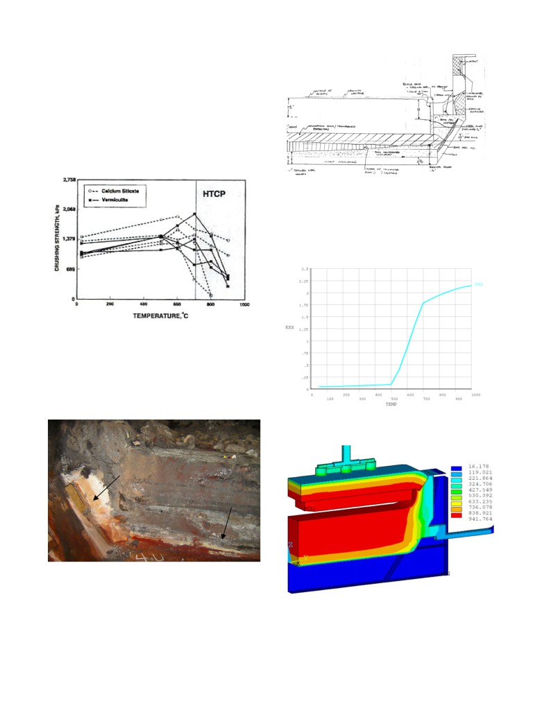
In the operating cell, the light insulating materials are exposed to
degradation both by high temperatures and by reaction with bath
chemicals. It has been shown that above about 700 °C, these
materials will lose much of their insulating property as first
presented in [11] and reproduced in Figure 9. In addition, cathodic
bath components, including sodium, permeate the lining materials.
If these components reach the insulation in liquid form, they will
penetrate the porous structure of the insulation, destroying the
insulating value.
Figure 11: Sketch from a A697 cell autopsy describing the
chemical degradation of the insulation layer from [8]
As discussed in [10], in order for the model to take into account
that chemical degradation that occurs in the calcium silicate
exposed at high temperature, the temperature dependent thermal
conductivity needs to be adjusted as presented in Figure 12.
Figure 9: Observed degradation of insulating material properties
above about 700 °C from [11]
As noted in [10] the sign of that degradation was seen in a cell
autopsy but those autopsy results for the P155 cell were not
presented in [10]. Fortunately, very similar autopsy results were
presented in [8] for the A697 cell, those autopsy results confirm
the chemical degradation of very large portion of the thick
insulation layer as presented in Figure 10.
Figure
12: Temperature dependent thermal conductivity of
calcium silicate material used in cell lining
Insulation in side is like new;
in bottom is penetrated by bath
Figure 10: Picture from a A697 cell autopsy showing the chemical
degradation of the insulation layer from [8]
Since it is not that easy to observe from that picture the chemical
degradation of the insulation layer, the sketch describing the state
Figure 13: A697 full cell slice model temperature solution using
of the cell lining prepared during another autopsy is presented in
the modified calcium silicate property
Figure 11.
The thermal conductivity curve presented in Figure 12 essentially
Of course this change would not occur overnight, the first case
assumed that below a temperature threshold, 500 °C in this case,
would be representative of the condition a few weeks after startup
the new calcium silicate properties remain intact and that above a
when cell operations have stabilized while the second case would
second temperature threshold, 700 °C in this case, we are dealing
be representative of the condition after full penetration of the bath
with a completely different new material. The ramp between the 2
constituents into the cathode lining.
temperature threshold transition zones is numerically required to
ensure that the finite element (FE) solver will be able to converge
that very non-linear problem.
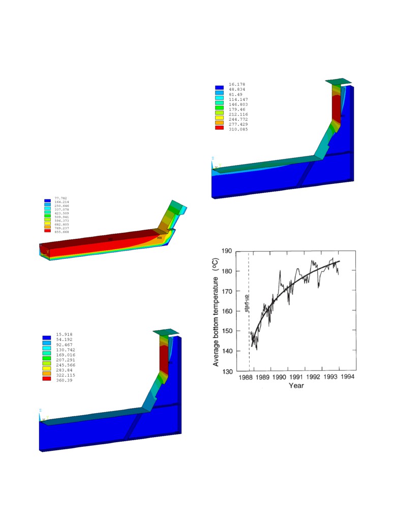
Since the cell internal heat was kept the same, the converged cell
heat loss remained the same but the heat loss partition is now very
different: the cell bottom floor dissipates more heat while cell side
wall now dissipates less heat due to the predicted decrease of the
cell superheat and the corresponding predicted increase of the
ledge thickness. This change in ledging results in changes in the
operational behavior of the cell, and may require additional
energy input to maintain stability. In any case the cell behaves
quite differently than predicted by the model prior to the
corrections made as a result of the validation process. The
obtained temperature solution is presented in Figure 13, while the
temperature solution of only the calcium silicate material is
presented in Figure 14.
Figure 16: Potshell temperature solution using the modified
calcium silicate property
In fact, that type change of the potshell floor temperature have
been measured and reported in
[4] on a
155 kA cell, those
measurements are presented in Figure 17.
Figure 14: Calcium silicate temperature solution using the
modified calcium silicate property
That change of repartition of the cathode heat loss would be quite
easy to observe as it significantly affects the potshell temperature.
Figure 15 presents the potshell temperature solution of the first
case when using the new calcium silicate property while Figure 16
presents the potshell temperature solution of the second case when
using modified calcium silicate property.
Figure 17: Averaged measured change of the potshell floor
temperature of 16 155 kA prebaked cells, Figure 17 of [4]
The need for more field validation work
In retrospective the story of the over insulated cathode lining with
a too thick layer thickness of calcium silicate that could not
possibly avoid chemical degradation regardless of the type of
physical barrier put in place to try to protect it is quite instructive
as it is not unique.
Figure 15: Potshell temperature solution using new calcium
silicate property
Calcium silicate is not the only material that is susceptible to
References
chemical attack and significant properties changes when put in
cell operating conditions. Anode cover material is another
[1] Geoff Bearne, Marc Dupuis, Gary Tarcy, ed., Essential
example of equal importance that also has been the object to
Readings in Light Metals, Volume 2: Aluminum Reduction
significant studies over the years including quite recently: [12,
Technology, ISBN 9 78-1-118-63574-2.
13].
[2] Lynnes Robinsoni, “Light Metals Project Distills Decades of
On the other hand some material would need more
Knowledge to Its Essential Elements”, JOM, Vol. 65, No. 3,
characterization work, for example the dry barrier material
2013, 352-356.
extensively use in Chinese lining designs. Despite the recent work
done [14], there is certainly a need for more work in order to
[3] V. Gaudreault, H. Vermette, V. Langlois and L. Lefrançois,
come up with a validated temperature dependent thermal
“The Rio Tinto’s P155 Smelters now Operating at 210 kA”,
conductivity property to be used in cell thermal balance modeling.
COM Light Metals, 2011, 395-401.
[4] Morten Sørlie, Hermann Gran and Harald Øye, “Property
Conclusions
Changes of Cathode Lining Materials during Cell
In order to be successful, the cell design of high amperage cells
Operation”, TMS Light Metals, 1995, 936-945.
must be conducted using the “cell development cycle” method [3].
[5] K. Tschöpe, C. Schøning, J. Rutlin and T. Grande,
The method comprises several steps, from modeling to
“Chemical Degradation of Cathode Lining in Hall-Héroult
measurement campaigns that must be used in repetitive cell
Cells - An Autopsy Study of Three Spend Pot Linings”,
design improvement cycles:
Metallurgical and Materials Transactions B, Vol 43B 2012,
290-301.
1) Cell design through modeling
2) Cell engineering and prototype cells construction
[6] Jay Bruggeman, “Pot Heat Balance Fundamentals”, Proc. 6th
3) Prototype cells operation
Aust. Al. Smelting Workshop, 1998, 167-190.
4) Prototype cells measurement campaigns
5) Prototype cells postmortem autopsy
[7] M. Dupuis, A. Koshie, V. Janakiraman, S. Karthikeyan and
6) Model calibration and validation
D. Saravanan, “Accurate Assessment of the Hirakud Smelter
Aluminium Reduction Cell Thermal Balance using only
Only data obtained from cell prototypes in steps 4 and 5 of the
Temperature Measurements”, COM Light Metals, 2004, 525-
cell development cycle can be used in order to get reliable
533.
predictions from cell thermal balance models.
[8] Richard Jeltsch, “Use of Cell Autopsy to Diagnose Potlining
The first way to verify the accuracy of a cell heat balance model
Problems”, TMS Light Metals, 2009, 1079-1084.
predictions is to directly compare them with data obtained from
prototype cell heat balance measurement campaigns [6, 7].
[9] Morten Sorlie and Harald Oye, Cathodes in Aluminium
Electrolysis 3th edition, ISBN 978-3-410-22016-9.
The only way to directly obtain the used material properties
required as inputs in models is to stop the prototype cells, dig out
[10] Marc Dupuis and Imad Tabsh, “Thermo-Electric Analysis of
samples and measure the properties of those samples at a range of
the Grande-Baie Aluminium Reduction Cell”, TMS Light
operating temperature [8, 14].
Metals, 1994, 339-342.
For example, it is well known that above about 700 °C, light
[11] A. T. Tabereaux and D. V. Stewart,
“High-Temperature
insulating materials such as calcium silicate will get exposed to
Critical Point
(HTCP) for Insulating Blocks Used for
chemical degradation and will lose much of its insulating
Cathode Insulation”, COM Light Metals, 1992, 103-114.
property.
[12] H. Wijayaratne, M. Hyland, M. Taylor, A. Grama and T.
In order for the model to take into account the chemical
Groutso,
“Effects of Composition and Granulometry on
degradation that occurs in the insulation exposed at high
Thermal Conductivity of Anode Cover Materials”, TMS
temperature, the temperature dependent thermal conductivity
Light Metals, 2011, 399-404.
needs to be adjusted.
[13] Q. Zhang, M. Taylor, J. Chen, D. Cotton, T. Groutzo and X.
The thermal conductivity of other materials such as the dry barrier
Yang, “Composition and Thermal Analysis of Crust Formed
material used in Chinese lining designs also must be characterized
from Industrial Anode Cover”, TMS Light Metals, 2013, 675-
after exposure to high temperatures and penetration by cathodic
680.
bath materials.
[14] R. Jeltsch and C. Chen, “Dry Barrier Mix in Reduction Cell
Cathodes”, TMS Light Metals, 2012, 1259-1263