Non-linear stability analysis of cells having different types of cathode surface geometry
Marc Dupuis1 and Valdis Bojarevics2
1 GéniSim Inc., 3111 Alger St., Jonquière, Québec, Canada G7S 2M9
marc.dupuis@genisim.com
2 University of Greenwich, School of Computing and Mathematics,
30 Park Row, London, SE10 9LS, UK
V.Bojarevics@gre.ac.uk
Keywords: Modeling, MHD, cell stability, irregular cathode surface, current density
Abstract
Cell stability study on a standard flat cathode surface cell
Different operational parameters are known to influence cell
Before comparing the stability of cells using different type of
stability like ACD, ledge toe position and metal level.
cathode surface geometry, the present study will first cover more
standard factors that are known to influence cell stability like
Irregular cathode surface design is also thought to influence cell
ACD, metal pad level, ledge toe position and busbar design.
stability but how significantly as compared to the above
operational parameters?
500 kA cell with regular flat cathode surface base case
In the present work, cell stability analyses are performed on 3
The cell design that will be used as comparison base is the same
types of cathode surface geometries: cathode with a flat surface,
as the one used in some previous work [5,7,8]. It is a 500 kA cell
cathode with longitudinal ridges and cathode with lateral ridges.
using a asymmetric busbar network design inspired from Chinese
busbar design
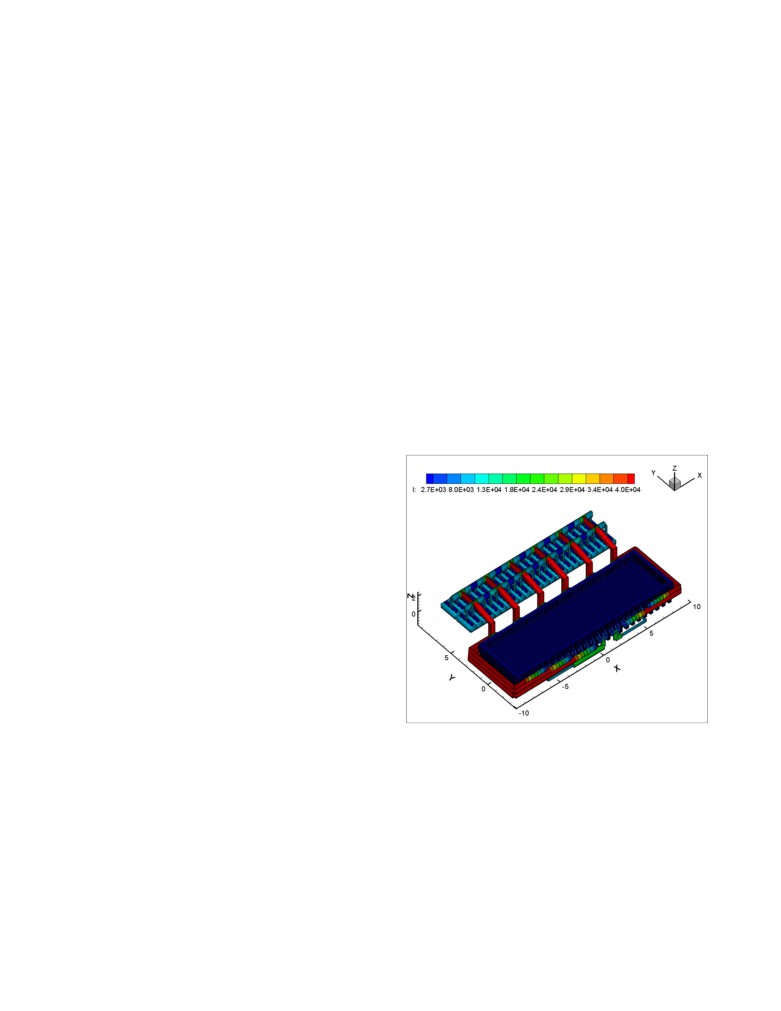
[9]. Figure
1 shows the model geometry as
Introduction
constructed by the most recent MHD-Valdis code version (July
2014):
Irregular cathode surface technology is still the subject of research
in China where it is quite popular. Chinese research papers
recently published at the TMS [1-3] are concluding that irregular
cathode surface technology is increasing cell stability, yet they are
not presenting any results of cell stability analysis.
If we analyze the impact of irregular cathode surface technology
one element at the time in mathematical model results, it has been
observed that:
1) The irregular cathode surface technology has some effect on
the drag of the cathode surface on the metal flow which is
could be beneficial to the cell stability [4];
2) The irregular cathode surface technology has significant
impact on the metal pad horizontal current which is more
probably harmful than beneficial to the cell stability [2-3,5-
6];
3) The irregular cathode surface technology may or may not
have a significant impact on the global steady-state metal
flow pattern and bath-metal interface deformation. Results
reported so far are not in agreement, [1] and [2] report a
significant change while [3] and [7] report far less changes;
Figure 1: Geometry of the 500 kA base case model showing
the current intensity solution in each conductor (in A)
4) A cell stability analysis is required to make any prediction of
the impact of irregular cathode surface technology on the cell
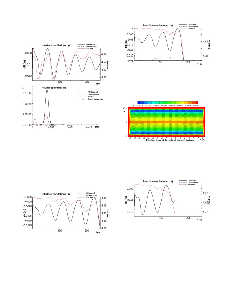
After a few seconds of calculation, the above graphic, showing the
stability. Only [5-7] have presented results of that kind of
busbar current, becomes available as well as the metal pad current
cell stability analysis, a full non-linear transient analysis and
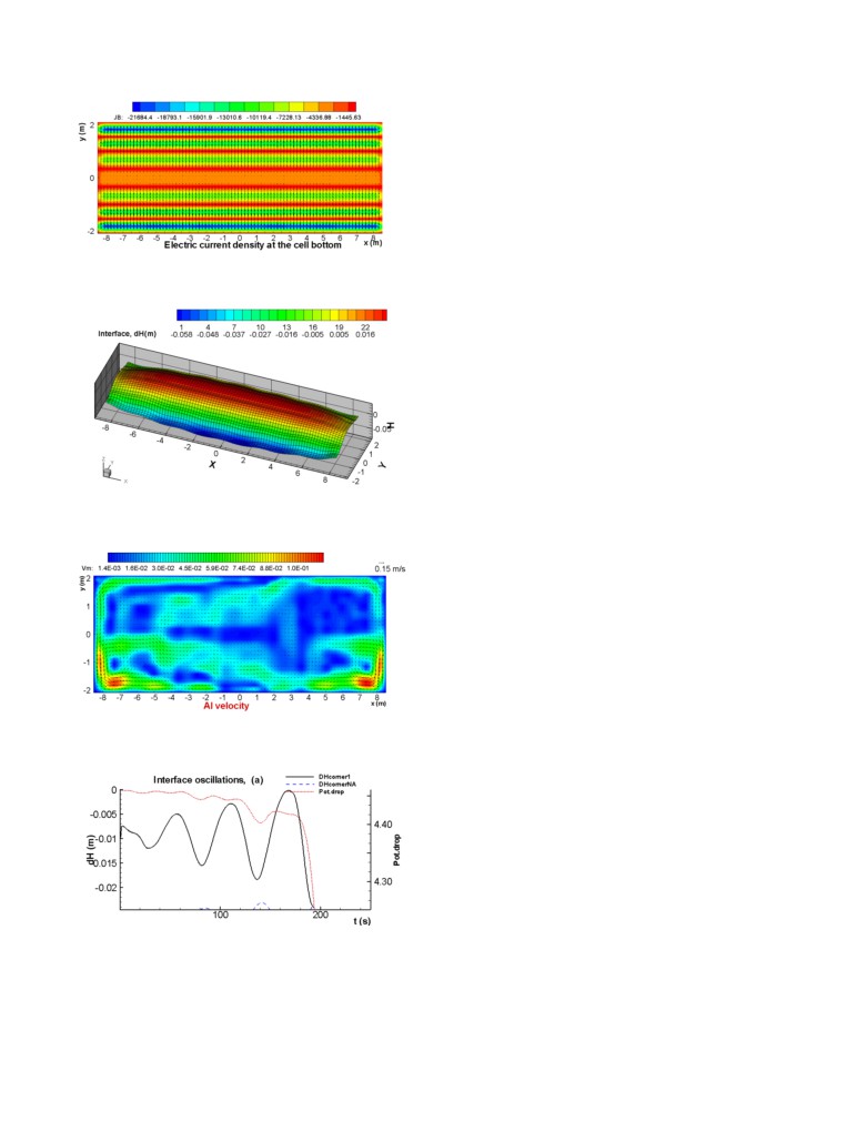
density as shown in Figure 2.
results indicate that irregular cathode surface technology has
little impact on the cell stability if other factors like the
The iso-contours are showing the current density at the surface of
changes of ledge toe thickness or metal pad height are
the cathode while the vectors are illustrating the horizontal
removed.
components of the current density at the middle of the metal pad.
In order to make the above interpretation more rigorous, a new
Then after a few minutes of calculation that takes into
more thorough cell stability study had been carried out. Results of
consideration the non-linear magnetization of the potshell and the
that more global cell stability study are now presented.
position of the return line (that have been moved as compared to
previous publications), the magnetic field solution becomes
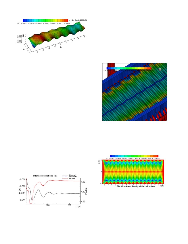
available. Figure 3 is showing Bz, the vertical component of the
magnetic field at the middle of the metal pad.
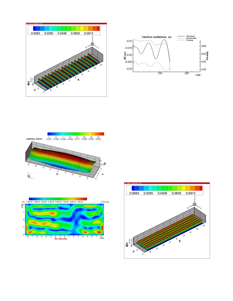
Figure 5: Steady-state flow pattern in metal pad (in m/s)
The fully non-linear transient analysis starts from that steady-state
solution. Contrary to previous code version, the interface will not
move at all if no initial perturbation is defined by the user. In
previous versions [5-7], the transient analysis was starting with a
Figure 2: Current density solution on the top surface of the
high frequency wave that was being damped for about
150
cathode (in A/m2)
seconds of transient evolution before a more unstable lower
frequency wave could developed (Figure 18 of [5] is a good
example of that) so a long transient analysis of about
1000
seconds was required to be able to evaluate the cell stability.
With the current code version, the user can define a perturbation
that immediately triggers a
3,1 mode rotating wave that is
typically the less stable wave mode. Figure 6 presents the results
of a 1100 seconds fully non-linear transient analysis using the
recommended 0.25 second time step. This type of transient
analysis requires about
3 days of CPU on an Intel T9300
processor running on Windows x64.
Figure 3: Vertical component of the magnetic field solution in
the middle of the metal pad (in T)
Then follow after about 15 to 20 minutes of calculation, the steady
state solution of the bath-metal interface and metal flow pattern as
presented in Figures 4 and 5 respectively:
Figure 6: Evolution of one point on the interface position (in
Figure 4: Steady-state bath-metal interface deformation (in
m) on the top and results of the spectral analysis of the wave
cm) (0 is the position of the flat interface)
evolution on the bottom
Since the CFD model is using the k-ω turbulence model k the
The evolution of the interface oscillations and the Fourier
turbulent kinetic energy is also available as scalar field as well as
spectrum presented in Figure 6 clearly indicated that a single 3,1
the two horizontal velocity components. In Figure
5, the
rotating mode wave having a frequency just above the 3,0 gravity
magnitude of the vectors is used as scalar field. MHD-Valdis 2D
shallow layer CFD model takes into consideration the topology of
wave mode is being exponentially damped after an initial period
of less than 100 seconds of more complex evolution.
both the cathode surface and the bath-metal interface.
Since the aim of the present study was to analyze a lot of different
cases, a 250 seconds transient analysis duration was selected as
standard duration to perform all those analyses. Figure 7 presents
the results of that much shorter transient analysis.
Figure 9: Stability analysis for base case minus 5 cm metal
pad level
Base case plus 15 cm ledge toe thickness
Adding 15 cm of ledge toe thickness strongly affects a lot the
metal pad current density as can be seen in Figure 10 below:
Figure 7: Evolution of one point on the interface position (in
m) on the top and results of the spectral analysis of the wave
evolution on the bottom of a shorter 250 seconds analysis
The interpretation of the results is the same, a single 3,1 rotating
Figure 10: Current density solution for base case plus 15 cm
wave is exponentially decaying after its initial formation phase
ledge toe thickness
for an unambiguous prediction of stable cell design for this base
In turn, this increase of metal pad horizontal current significantly
case model setup in less that 24 hours of CPU time.
decreases the cell stability. As shown in Figure 11 below, the
wave is growing even faster than in the previous case, the cell
Base case minus 5 mm ACD
short circuits in about 150 seconds.
As can be seen in Figure 8, reducing the ACD from 4.5 cm to 4.0
cm is enough to flip the cell stability prediction from stable to
unstable.
Figure 11: Stability analysis for base case plus 15 cm ledge toe
thickness
Figure 8: Stability analysis for base case minus 5 mm ACD
Improved magnetic field case
The previous four cases are demonstrating that the selected base
Base case minus 5 cm metal pad level
case busbar design is stable but is quite close to the stability limit
As illustrated in Figure 9, reducing the metal pad level from 25
which is a good thing to highlight the impact of destabilizing
actions on the cell. The next case, on the contrary, highlights the
cm to 20 cm is also enough to flip the cell stability prediction
from stable to unstable. Since the wave is growing faster than in
stabilizing effect of improving the magnetic field by improving
the previous case, the cell short circuits in about 180 seconds.
the busbar network design in order to reduce the Bz gradient
intensity.
Lateral ridges case
The lateral ridges case was built as follow. There are 48 collector
bars per side in that cell and normally 24 blocks using a double
bars per block arrangement. In order to generate well resolved
lateral rides considering the 80x30 mesh resolution of the CFD
model, the 24 blocks double bars per block arrangement was
replaced by a 48 blocks single bar per block arrangement with a
unit of three repetitive patterns, where the first and third blocks
remained the same height, but the height of the second block has
been increased by 10 cm. This scheme generates 16 lateral ridges
in the cell. Figure 14 is showing a zoom in view of the cathode
Figure 12: Vertical component of the magnetic field solution
surface geometry.
from the improved busbar design case
In order to improve the magnetic field, the return line was moved
away 5 m from 60 to 65 m in addition to moving a few busbars
around the cell. The Bz field looks very similar in Figure 12 as
compared to Figure 3 but the quarter averaged values available in
the printout are now more symmetric. For the base case, the
results were:
Quarter averages of BSZ in T
^ Y
|
0.00127|
-0.00056
----------|----------> X
0.00105|
-0.00033
|
while for the improved magnetic field case, the results were:
Quarter averages of BSZ in T
Figure 14: Geometry of the lateral ridges case showing the
current intensity solution in each conductor (in A)
^ Y
|
MHD-Valdis offers the option to define the position of the ledge
0.00098|
-0.00048
toe all around the perimeter of the cell. That option was used here
----------|----------> X
to define the base case thickness on top of ridges and a plus 15 cm
0.00073|
-0.00020
thickness between ridges in order to represent the ledge toe
|
thickness presented in Figure 5 of [11]. The resulting metal pad
current density is presented in Figure 15:
This is a clear improvement of the magnetic field as the gradient
of the Bz in the longitudinal direction of the cell (X direction),
that is the generator of the 3,1 mode rotating wave [10], has been
significantly decreased. As a result, the stability analysis reports a
more stable cell as the wave damping rate has significantly
increased as shown in Figure 13:
Figure 15: Current density solution on the top surface of the
cathode (in A/m2) for the lateral ridges case
The resolution of the ridges geometry by the 80x30 CFD model
mesh is shown in Figure 16. Clearly a much finer mesh would be
required to represent adequately a bigger number of narrower
ridges (see per example Figure 6 of [3]) which would in turn
Figure 13: Stability analysis for the improved magnetic field
increases the time required to carry up a cell stability analysis.
case
stable than the base case plus 15 ledge toe thickness. Results of
the transient cell stability analysis are presented in Figure 19.
Figure 19: Stability analysis for the lateral ridges case
The cell is still predicted to be unstable with a wave growth rate
very similar to the one of the base case plus 15 ledge toe thickness
as the cell short circuit in about 140 seconds. Again in this study,
the prediction of MHD-Valdis is that the presence of lateral ridges
Figure 16: Spatial resolution of the 16 ridges geometry in the
should not affect much the cell stability.
80x30 CFD model mesh
The impact of the ridges is also clearly visible in the steady-state
Longitudinal ridges case
solution presented in Figures 17 and 18. Note that, in order to
keep unchanged the metal volume, the metal pad level has been
The longitudinal rides case was built as follow. In [5] and [6], the
increased to 28.33 cm from the 25 cm base case.
impact of a cell having 8 longitudinal ridges on the metal pad
current density was analyzed using a detailed finite element
thermo-electric model. Unfortunately, 30 mesh divisions in the
lateral direction is not enough to well discretize 8 longitudinal
ridges, so this case will study the impact of adding 6 longitudinal
ridges on the cell stability instead. Figure 20 shows the spatial
resolution of those 6 ridges, while Figure 21 shows the resulting
metal pad current density. Note that this time, the base case ledge
toe thickness was kept.
The impact of the ridges is also clearly visible in the steady-state
solution presented in Figures 22 and 23. Note that in order to keep
unchanged the metal volume, the metal pad level has been
increased to 28.33 cm again this time.
Figure 17: Steady-state bath-metal interface deformation (in
cm) for the lateral ridges case
Figure 18: Steady-state flow pattern in metal pad (in m/s) for
the lateral ridges case
To be fair the lateral ridges case stability should not be compared
to the base case but to the base case plus 15 ledge toe thickness,
Figure 20: Spatial resolution of the 6 ridges geometry in the
and there is no substitute for performing the cell stability analysis
80x30 CFD model mesh
to know if this lateral ridges case will turn out to be more or less
Conclusions
A thorough cell stability study has been carried out for a standard
flat cathode surface cell. As expected, reducing the ACD,
reducing the metal pad level and increasing the ledge toe
thickness has a destabilizing effect on the cell. As expected as
well, reducing the longitudinal gradient of the Bz has a stabilizing
effect on the cell.
As reported in previous study [5,7], the prediction of MHD-Valdis
is that the presence of lateral ridges should not affect much the
cell stability.
Figure 21: Current density solution on the top surface of the
When the impact of the longitudinal ridges on the metal pad
cathode (in A/m2) for the longitudinal ridges case
current density reported in [5,6] is taken into consideration, the
prediction of MHD-Valdis is that their presence has a
destabilizing effect on the cell.
References
[1] Qiang Wang, Jianping Peng, Baokuan Li and Naixiang Feng,
“Effect of innovative cathode on bath/metal interface
fluctuation in aluminum electrolytic cell” TMS Light Metals
2014, 491-494.
[2] Wang Qiang, Li Baokuan, Wang Fang, Feng Naixiang,
“Magnetohydrodynamic model coupling multiphase flow in
aluminum reduction cell with innovative cathode
protrusion”, Light Metals 2013, 615-519.
Figure 22: Steady-state bath-metal interface deformation (in
cm) for the longitudinal ridges case
[3] Baokuan Li, Fang Wang, Xiaobo Zhang, Fengsheng Qi and
Naixiang
Feng,
“Modeling
of
interface
of
electrolyte/aluminum reduction cell with novel cathode
structure”, TMS Light Metals 2012, 865-868.
[4] Valdis Bojarevics,
“MHD of Aluminium Cells with the
Effect of Channels and Cathode Perturbation Elements,”
TMS Light Metals 2013, 609-614.
[5] Marc Dupuis and Valdis Bojarevics,
“Influence of the
cathode surface geometry on the metal pad current density”,
TMS Light Metals 2014, 479-484.
[6] Valdis Bojarevics and Sharnjit Sira,
“MHD stability for
irregular and disturbed aluminium reduction cells”, TMS
Figure 23: Steady-state flow pattern in metal pad (in m/s) for
Light Metals 2014, 685-690.
the longitudinal ridges case
[7] Marc Dupuis and Valdis Bojarevics, “Newest MHD-Valdis
cell stability studies”, ALUMINIUM, 90 (2014) 1-2, 42-44.
[8] Marc Dupuis and Valdis Bojarevics, “Retrofit of a 500 kA
cell design into a 600 kA cell design”, 87 (2011) 1-2, 52-55.
[9] Hongliang Zhang, Chenn Q. Zhou, Bing Wu and Jie Li, “A
Virtual Aluminum Reduction Cell”, JOM, Vol. 65, No. 11,
2013, 1452-1458.
[10] Nobuo Urata, “Wave mode coupling and instability in the
internal wave in aluminum reduction cells”, TMS Light
Figure 24: Stability analysis for the longitudinal ridges case
Metals 2005, 455-460.
According to the stability analysis results, the addition of
[11] J. Zhou et al., “Depth Analysis and Potential Exploitation of
longitudinal ridges destabilize the cell.
Energy-Saving and Consumption-Reduction of Aluminum
Reduction Pot,” TMS Light Metals, 2012, 601-606.