setup and 195 mV while using the temperature- and pressure-
dependent contact resistance setup. So a saving of about 13 mV
came from the fact that there is less voltage drop in the collector
bar section outside the cathode block. Then, according to the TEM
model, an additional reduction of about 4 mV can be expected due
to the improved contact, which is less than the previous case.
design change that improves the contact and hence decreases the
cathode lining drop. As a simple example, it is possible to study
the impact of changing the position of the minimum thickness area
of the slot. In this third design change run, that position is moved
up from the mid point position to the top quarter point position still
keeping the bigger 174 mm x 174 mm collector bar and still
keeping the same average 13 mm cast iron thickness on the two
side sections (see Figure 12).
contact resistance setup but now predicts 192 mV while using the
temperature- and pressure-dependent contact resistance setup. So
this is an additional decrease of 3 mV for a total of 7 mV decrease
due to the increase of the collector bar section: hence a grand total
of 20 mV reduction over the base case value for a reduction of
9.4% while still keeping the same collector bar slot aspect ratio and
cross-section.
bar slot configurations that can now be tested using this new TEM
collector bar slot design tool, like testing if a "W" profile would
provide a better contact than the standard "V" shape profile. Yet,
testing a "W" profile would require a little change in the model
topology while there are still many new cases that can be analyzed
using the current model topology.
section is more efficient than a square collector bar cross-section.
But it would be interesting to see if the TEM collector bar slot
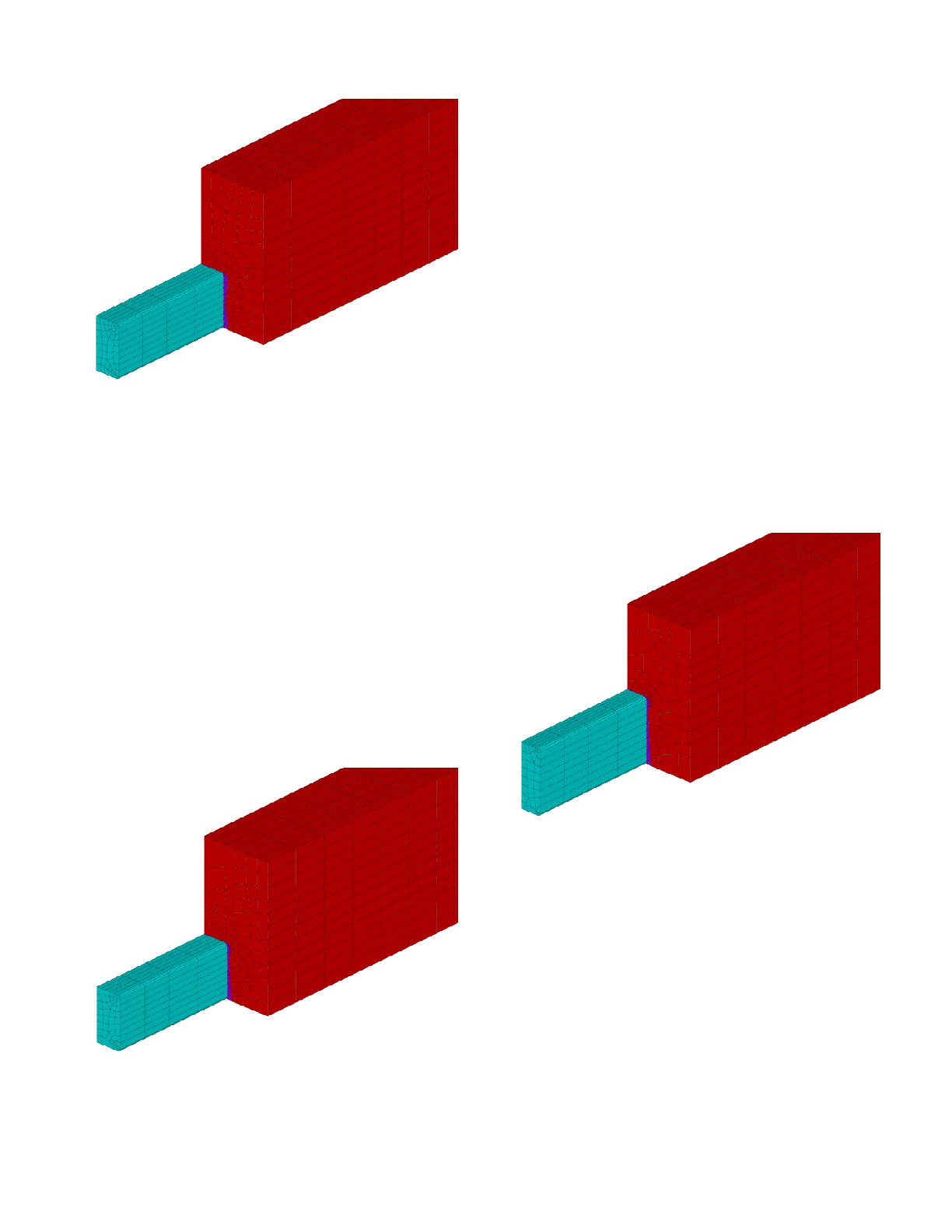
model confirms this. In this forth design change, the 174 mm x
174 mm collector bar is replaced by a 144 mm wide x 210 mm high
collector bar keeping about the same cross-section by significantly
changing the aspect ratio. Figure 13 is presenting the resulting
model geometry still keeping 13 mm of average cast iron thickness
on the sides and the minimum thickness area at the upper quarter
point.
setup and 187 mV while using the temperature- and pressure-
dependent contact resistance setup. It is fair to compare those
results with the ones of the previous case as only the collector bar
aspect ratio has been changed. It is also fair to compare the two
constant contact resistance results and the two variable contact
resistance results between themselves.
arbitrarily ratio of 2 between the horizontal and the vertical contact
resistance, that change of aspect ratio should reduce the cathode
voltage drop by 7 mV. According to the variable contact resistance
model setup, that change of aspect ratio should reduce the cathode
voltage drop by 5 mV. So there is no strong disagreement between
the two versions of the model which is a good thing for the user of
the standard TE cathode side slice model. Of course, changing the
collector bar aspect ratio will also affect the lining life so maybe in
that context this design change is not an improvement!