bar is useful, the aim of the first design change run is to test that.
In this run, the 160 mm wide x 160 mm high collector bar is
replaced by a 160 mm wide x 174 mm high collector bar leaving
only 2 mm of cast iron above the bar (completely eliminating the
cast iron above the bar would require a new model topology). The
new model geometry is presented in Figure 9.
setup and 197 mV while using the temperature- and pressure-
dependent contact resistance setup. So a saving of about 6 mV
came from the fact that there is less voltage drop in the collector
bar section outside the cathode block. Then, according to the TEM
model, an additional reduction of about 9 mV can be expected due
to the improved contact in the top horizontal interface section that
resulted from the decrease of the cast iron thickness and hence the
increase of the contact pressure.
carbon block interface contact would behave any differently than a
cast iron/cathode carbon block contact, this run is really testing the
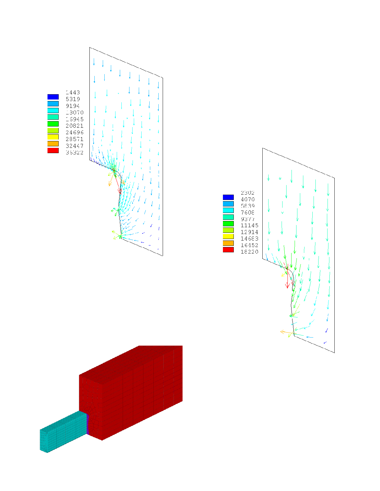
option of not putting any cast iron above the bar. Figure 10 shows
the corresponding current density in the cathode block edge.
be achieved using the minimum cast iron thickness possible. This
reduction must be done by increasing the collector bar section, not
by decreasing the collector bar slot width because, inside the block,
the effective collector bar section is the slot section as the current
travels in the cast iron too. So this second design change run is
testing a 174 mm wide x 174 mm high collector bar using the same
collector bar slot leaving on average only 13 mm of cast iron.
Figure 11 is presenting the corresponding model geometry.