quarter cathode block model of a "single slot per block" design
type. Actually, there are two collector bars per block because the
block is 3.67 m long and the two bars are 2.175 m long each
leaving a section without bar in the middle of the block. Those two
collector bars have a square cross-section of 160 mm x 160 mm.
The cathode block has also a square cross-section of 48 cm x 48
cm. The size of the collector bar slot is 176 mm of height leaving
room for 16 mm of cast iron above the bar and on average 200 mm
of width leaving 20 mm of cast iron on each side of the bar. Yet,
because of the typical "V" shape of the vertical faces of the slot, the
cast iron thickness actually varies from a minimum of 15 mm to a
maximum of 25 mm. It is assumed that there is 28 such cathode
blocks in a cell running at 300 kA, so the current in each bar is
300/28/2 = 5.36 kA for a maximum current density in each
collector bar of 5360/16/16 = 20.92 A/cm2.
the slot are not represented in that much details but the full lining
and potshell are also represented (see Figure 2). This is required in
order to be able to accurately calculate the cathode heat loss. That
calculation is not a requirement of the TEM cathode model, yet
computation of the temperature is still required. Fortunately, it is
possible to compute that temperature without having to represent
the full lining by using appropriate boundary conditions (see Figure
3).
user defined contact resistance values as in the TE model. Typical
values of 4 µ-ohm m2 for the vertical interface and 8 µ-ohm m2 for the
of 2 between vertical and horizontal contact resistances). As
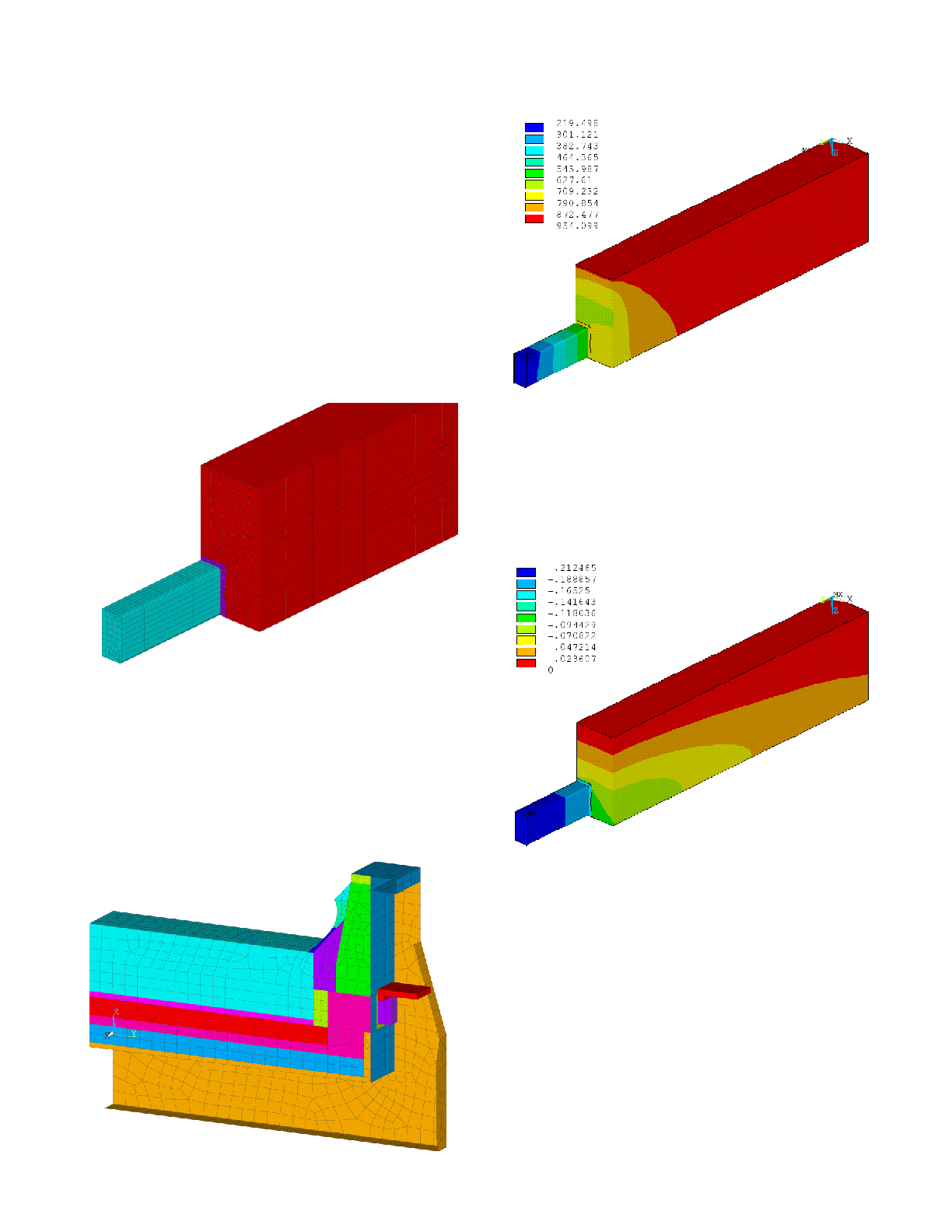
presented in Figure 4, for setup, the model predicts a cathode lining
drop of 212 mV.
the cathode block. Some current is travelling vertically straight
down from the top of the slot into the top section of the cast iron.
This may or may not be real, no measurement being available to
confirm or disprove that. The only thing that is known is that this
would be the current density, if the value of the horizontal contact
resistance would be twice the value of the vertical contact
resistance.
and pressure-dependent contact resistance property in the model
and calibrate the model so that it can predict close to 212 mV of
cathode lining drop. Many parameters could be used to do that
calibration. The one selected in the present work is Ta the effective
°C was required to get the results presented in Figure 6.