thickness is reduced to 10 mm while keeping the same flute
geometry except for the flutes depth that is increased to 10 mm
keeping the same maximum 20 mm maximum cast iron thickness.
The average cast iron thickness remains unchanged at 14 mm for
this second case geometric setup.
or 4.5% compared with the 8 flutes design constant resistance case
reflecting the increased of the interface contact surface. This is very
misleading because the run with the pressure and temperature
dependant contact resistance setup ratter predicts 288 mV for the
anode voltage drop which is 3 mV more than the 8 flutes variable
contact resistance case. Hence according to the TEM model with
the pressure and temperature contact resistance setup, adding more
flutes, of that design at least, is not reducing the anode voltage
drop, on the contrary, it is increasing it slightly. This slight increase
of anode voltage drop prediction is quite consistent with what was
reported in [8] for a very similar stub hole design change study.
not highlighting the power of the ANSYS® based TEM model as an
example the 8 flutes model option), it is possible almost
instantaneously to edit the APDL model input file to change the
model geometry (stud diameter, stud hole depth, minimum cast iron
thickness etc.), the model material properties (carbon block thermal
conductivity, cast iron thermal expansion coefficient, cast
iron/anode carbon contact resistance etc.) or the model boundary
conditions (amperage, bath temperature, bath immersion level etc.)
and submit another run.
turnaround time. Those quarter stub hole models (or 1/12 anode
model for a 3 studs per anode design) solves in only around 4000
CPU seconds on a 64 bits dual core Intel Centrino T 9300 Cell
Precision M6300 portable computer running ANSYS® 12.0
example.
most sensitive parameter in the flute design is the angle departure
from the radial axe of the two side faces of the flute. This angle is
an indirect parameter in the APDL model construction setup, it can
be calculated to be 14º for the 8 flutes case (arctan((18-14)/2)/8))
and 11º for the 16 flutes case (arctan((18-14)/2)/10)). Detailed
model results analysis revealed that those angles are too shallow to
permit any significant pressure buildup on these two flutes side
faces and that without a good pressure, essentially no current is
passing through those contact interface surfaces because that
without significant pressure, the interface contact resistance is
much too high.
third case presented here, is almost identical to the first case (8
flutes option), only the width of the flutes tip has been reduced
from the radial axe of the two side faces of the flutes is increased
from 14º to 41º (arctan((18-4)/2)/8)). This time, the model predicts
290 mV of anode voltage drop for the constant 2 micro-ohm m2
compared with case 1. Once again, this is very misleading because
the pressure and temperature dependant contact resistance model
setup run ratter predicts 278 mV which is a 7 mV or 2.5%
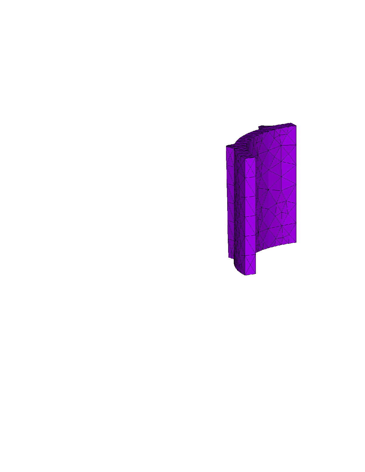
decreased obtained by that very simple flute design change (see
figure 7 for the new flute design mesh, figure 8 for the cast
iron/carbon anode contact pressure and figure 9 for the new cast
iron current density).
with 16 flutes, only the width of the flutes base has been increased
to 20 mm and the width of the flutes tip has been reduced to 4 mm
in order to get a 39º radial departure angle (arctan((20-4)/2)/10))
for the flutes side faces. The model predictions are 281 mV of
anode voltage drop for the constant 2 micro-ohm m2 contact
dependant contact resistance run.
according the TEM model with the proper pressure and
temperature dependant contact resistance setup, a very sight change
in the flutes design aiming at increasing the contact pressure of the
flutes side faces should decrease the anode voltage drop by 17 mV
or 5.9% (see figure 10 for the total voltage drop, figure 11 for the
cast iron/carbon anode contact pressure and figure 12 for the new
cast iron current density). This represents a reduction of about 0.3
MM $ per year of operating cost for a typical modern smelter
simply by changing the shape of the stub hole former! Of course, a
much more detailed optimization study should be able to identify
designs offering even more voltage drop reductions!