hole cast iron/anode carbon contact resistance complex physic in
ANSYS® version 12.0, it was quite strait forward for the author to
and to used them as efficient stub hole design tools.
The first demonstration anode stub hole model presented here is a
quarter stub hole model that would represents the quarter of an
anode for a 1 stub per anode block anode design, 1/8 of an anode
for a 2 stubs per anode block anode design, 1/12 of an anode for a
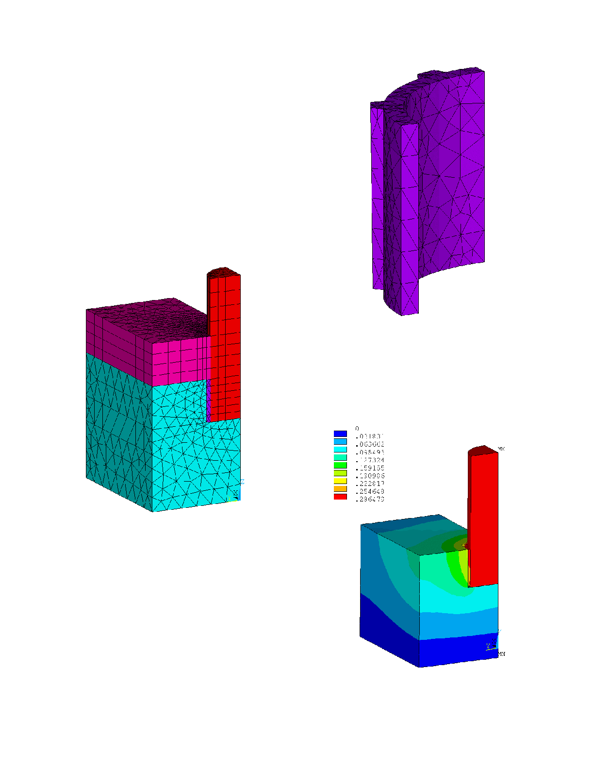
3 stubs per anode block anode design etc. (see figure 1 for the full
model mesh). In such a quarter stub model, it is easy to support
stub hole design having 4, 8, 12, 16 standard inclined flutes. The
first model presented here is using the 8 flutes option (see figure 2
for the cast iron only model mesh).
thousands of different actual anode stub hole geometries. Per
example, it is possible to vary the stub diameter, the stub hole
depth, the minimum cast iron thickness between flutes, and the
flute dimensions: width at the base, width at the tip and depth.
cm and the stub hole depth was kept to 12 cm. For the first case
presented, the minimum cast iron thickness was set to 12 mm, the
flute width at the base was set to 18 mm, the flute width at the tip
was set to 14 mm and the flute depth was set to 8 mm. This
geometric setup gives an average of 14 mm of cast iron thickness
between the stub and the anode carbon which, according to Brooks
[12], is the main stub hole design criteria.
model run, the "traditional" constant contact resistance setup was
used, a typical value of 2 micro-ohm m2 being selected for that
total voltage drop from the top of the stub to the bottom face of the
anode block (see figure 3).