a fully coupled thermo-electro-mechanical model as it was possible
to do for a cell in its preheat phase [5,6], relatively speaking of
course!
liquid zone where a lot of extra physics take place. The main
impact of the vertical potshell deformation is the generation of a
drastically longitudinally varying metal pad thickness. This
variation in the metal pad thickness have an impact on the local
sludge accumulation in the two ends that will have an impact on the
local electrical resistance above the cathode that will have an
impact on the longitudinal collector bars current pickup. All this
drastically affects the MHD cell stability characteristic of the cell.
model that complete interaction, but as a first step, it is possible to
take into account some effects of the vertical potshell deformation
in the MHD cell stability model.
has a strong influence on the MHD cell stability and the intensity of
that horizontal current density is directly proportional to the metal
pad thickness. With a vertically deformed potshell, there is a strong
longitudinal variation of that horizontal current density even for the
"static" bath/metal interface configuration.
developed to take into account the longitudinal deformation of the
cathode block surface as computed by the mechanical model [2]
and hence take into account the strongly varying metal pad
thickness and corresponding horizontal current density on the non-
linear MHD cell stability analysis.
cooling fins and no forced convection) 500 kA demonstration cell
is presented in Figure 9 of [2]. There is about a 2.25 cm difference
between the maximum potshell floor surface elevation at the center
of the cell and the minimum elevation at the two ends.
displacement of the cathode block top surface is identical to the
computed relative vertical displacement of the potshell floor and
that the vertical cathode block surface displacement is uniform
along the width of the cell because there is no data available at this
time to justify to do otherwise. Yet, it is important to notice that
this is not a limitation of the new MHD-Valdis model extension
that could accept any types of X-Y variable vertical surface
topology, like a cathode surface erosion profile for example.
extended MHD-Valdis model based on the base case vertical
displacement presented in Figure 9 of [2].
before and after considering the new bottom profile input, it is
worth specifying that the 500 kA busbar design used in the present
work is the one presented in Figure 1 of [8]. The base case 4.5 cm
ACD, 20 cm metal pad thickness and flat bottom profile bath/metal
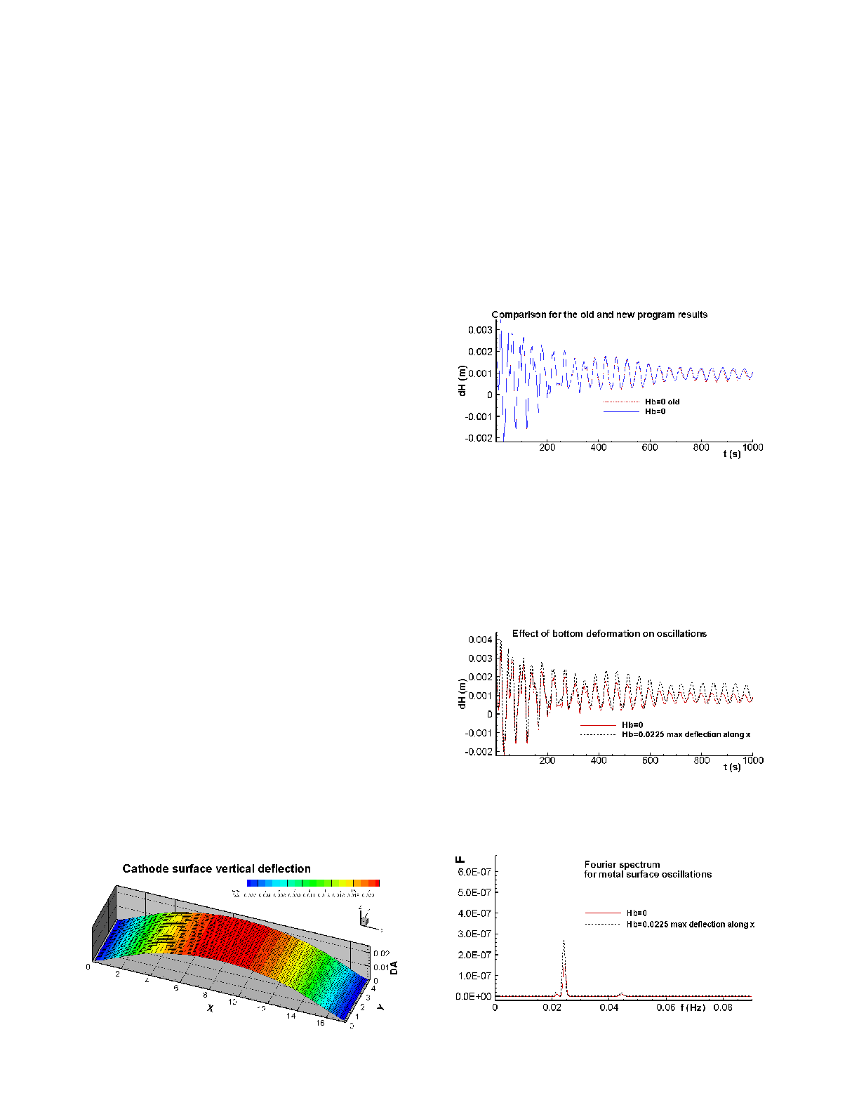
interface oscillation evolution is presented in Figure 2. This type of
oscillation evolution is characteristic of a stable cell prediction. The
figure compares the results obtained with the updated MHD-Valdis
model version using a flat bottom input with the results obtained
using the previous MHD-Valdis version [8]. They are of course
virtually identical.
after the variable bottom upgrade.
the same base case with flat bottom profile with the one predicted
when using the bottom profile presented in Figure 1. Figure 4
compares the Fourier power spectra of the two interface waves
presented in Figure 3. Results indicate that the latter case is
predicted to be less stable than the base case.
without up to 2.25 cm of vertical displacement.
interface wave Fourier power spectra.