New Busbar Network Concepts Taking Advantage of Copper Collector
Bars to Reduce Busbar Weight and Increase Cell Power Efficiency
Marc Dupuis
Consultant
GeniSim Inc., Jonquière, Québec, Canada
Corresponding author: marc.dupuis@genisim.com
Abstract
At the 2015 ICSOBA conference a reversed compensation current (RCC) busbar network
concept was presented. There is no return potline as the full return current passes under the cells
back to the rectifiers. The concept preferably uses upstream and downstream anode risers to
produce a symmetric upstream/downstream steady-state bath-metal interface deformation. This
busbar arrangement gives a very stable cell operation but requires more busbar weight.
In order to reduce the busbar weight, the concept has been improved by the use of copper
collector bars, which allows extracting 100 % of the cell current on the downstream side of the
cell and then feeding 50 % of the current to the standard upstream risers and 50 % to busbars
passing under the next cell to the downstream risers. The improved concept has alternated
upstream and downstream risers. It decreases busbar voltage drop and increases cell power
efficiency.
This concept can also be used for the external compensation current (ECC) busbar design,
which does not require downstream anode risers and reduces the busbar weight and cell voltage
further. This paper presents detailed results for Bx, Bz, metal pad flow, cell voltage and power
efficiency, for improved RCC and ECC concepts.
Keywords: MHD cell stability; busbar design; mathematical modeling; power efficiency;
copper collector bars.
1.
Usage of Copper Collector Bars
In its 2011 ALUMINIUM article [1], the author presented a 500 kA cell design using massive
collector bar inserts, covering 76 % of steel collector bar cross-section (see Figure 1). At the
time, it was speculative whether such a collector bar design could actually be built, but it is no
longer the case today after Storvik AS publication at the ISCOBA 2015 conference, presenting
technology for casting copper inserts into steel [2]. Furthermore, at the TMS 2016 conference
KAN-NAK advocated that copper collector bars do not even need to be protected by steel shell
and rodded to the block with cast iron [3]. The results presented in Figure 8 of [1] demonstrated
that the usage of copper bars having similar sizes as standard steel collector bars completely
eliminate horizontal current in the metal pad while Figure 6 of [1] (reproduced in Figure 1
below) presents model prediction of a 63 mV cathode drop operation for that 500 kA cell.
1.1.
Extracting 100 % of the cell current on the downstream side
What the author did not realized in 2011 is that with the usage of copper collector bars, 100 %
of the cell current can be extracted on the downstream size without generating excessive
horizontal current in the metal pad or generating excessive cathode voltage drop. In order to test
this idea, the 3D thermo-electric model previously used in [1] was adapted keeping exactly the
same lining design and collector bar size.
1
copper
steel
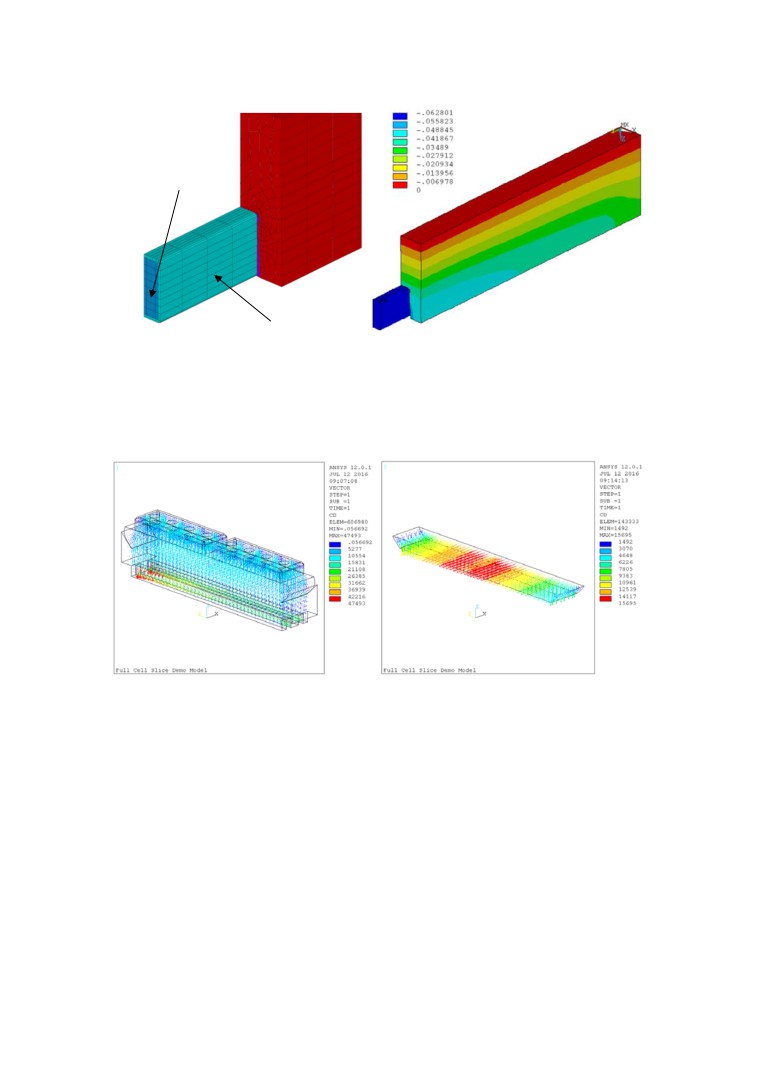
Figure 1. Thermo-electro-mechanical model with copper cross-section shown (left) and
predicted cathode voltage drop (right from [1]).
The cell has now a single collector bar across the whole width of the pot. In the model, the
carbon-cast iron contact resistances of 4 µΩm2 for the vertical interface and 8 µΩm2 for the
horizontal interface were used. The resulting calculated current density when all the current is
extracted from the downstream side is presented in Figure 2.
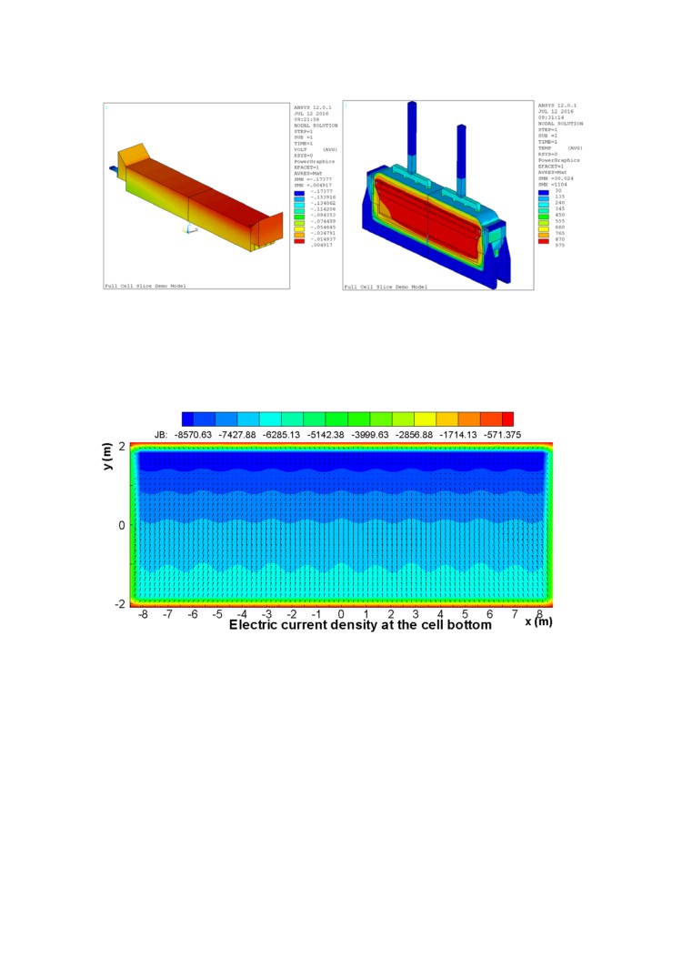
Figure 2. Thermo-electric model with current density in the whole domain (left) and in the
metal pad only (right).
With that size of collector bars, the resulting horizontal current density in the metal pad has the
same order of magnitude that the one obtained when using a standard steel collector bar designs.
Figure 3 presents the predicted corresponding cathode voltage drop and temperature.
2
Figure 3. Thermo-electric model voltage drop (left) and temperature (right).
The cathode voltage drop is predicted to be 174 mV which is still a very low value despite the
fact that now 100 % of the current is exiting the cell on the downstream side. Those results have
been confirmed by MHD-Valdis model of the same configuration as part of the MHD cell
stability study. Figure 4 shows the metal pad and cathode surface current density calculated by
MHD-Valdis.
Figure 4. Current density calculated with MHD-Valdis. Contours: current density
entering the cathode block. Arrows: Horizontal current density in the metal pad.
2.
Busbar Network Designs Taking Advantage of 100 % Downstream Cell Current
Extraction
2.1.
Reversed compensation current (RCC) busbar network case
The initial RCC busbar network concept introduced at the last ICSOBA conference [4] is based
on the usage of compensation busbar passing under the cells carrying 100 % of the cell line
current but in the opposite direction. This introduces the option of building a smelter with a
single potroom containing a single row of cells as the current can be returned to the rectifiers by
the RCC busbar.
It was also discussed that that single innovation is producing very stable cell designs at any cell
size and amperage as RCC compensation systematically generates a magnetic field in the metal
3
pad having a very small vertical components (Bz). Unfortunately using RCC without any other
changes generated very asymmetric upstream/downstream steady-state bath-metal interface
deformation (see Figure 11 of [4]).
In order to eliminate that potentially operational problem, a second innovation was introduced in
[4], the usage of downstream risers. The introduction of such downstream risers corrects the
shift in the longitudinal magnetic field component (Bx) generated by the RCC and produces a
symmetric upstream/downstream steady-state bath-metal interface deformation.
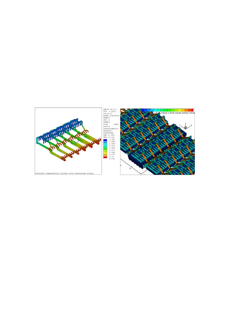
Figure 5 shows one of the two possible busbar configurations using both RCC and downstream
risers as proposed in [4]. In this busbar configuration, the current, coming from the downstream
side of the cell, is going to the usual anode risers located on the upstream side of the next cell
while the current coming from the upstream side of the cell is passing under that cell and the
next cell to feed the new anode risers located on the downstream side of that next cell.
Figure 5. Original RCC busbar network concept with downstream risers [4].
While addressing all the MHD related design criteria for any cell size and amperage, the above
configuration does require more busbar weight than existing busbar network designs. By taking
advantage of the fact that with the usage of copper collector bars 100 % of the cell current can
now exit on the downstream side of the cell, a new weight optimized RCC busbar network
concept with downstream risers was developed. As in the first design, 50 % of the anode current
is fed from the usual anode risers located on the upstream side and the other 50% is fed from the
new anode risers located on the downstream side; but this time those risers are used in
alternation, so they no longer face each other as it can be seen in Figure 6.
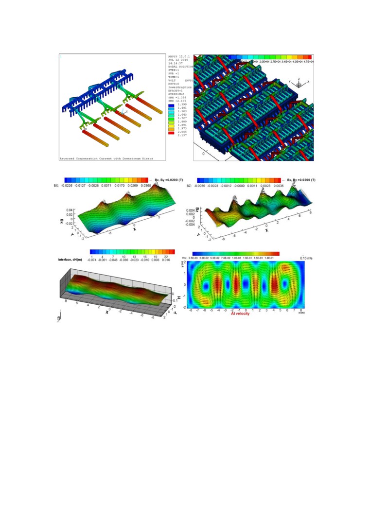
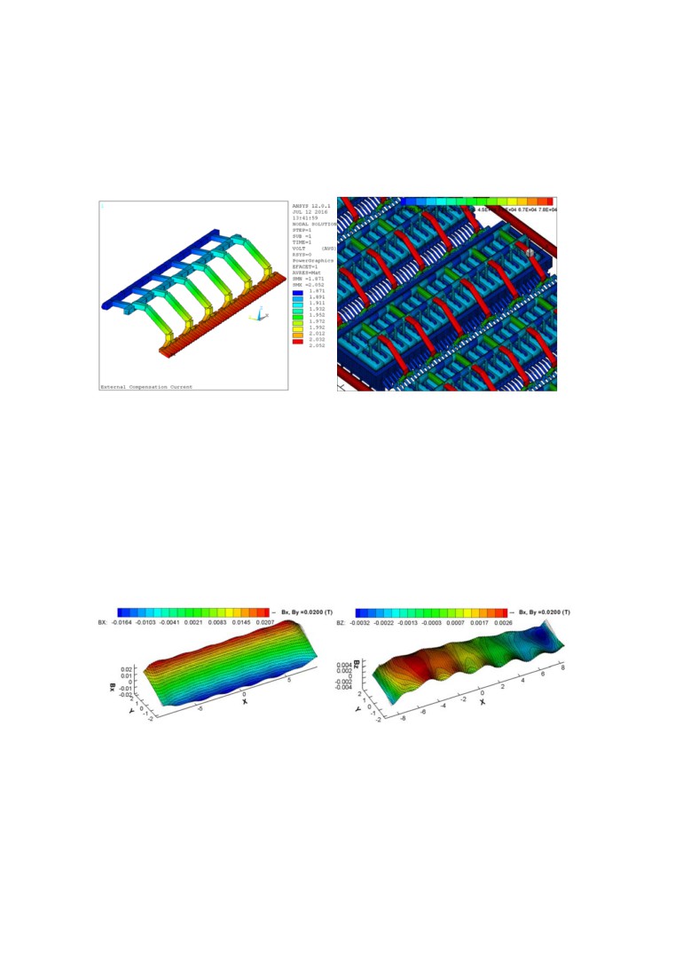
It can be noticed that the compensation busbars passing under the cell were not changed as that
configuration produced the quite acceptable Bx and Bz components of the magnetic field
presented in Figure 7. Other locations of the compensation busbar could be investigated.
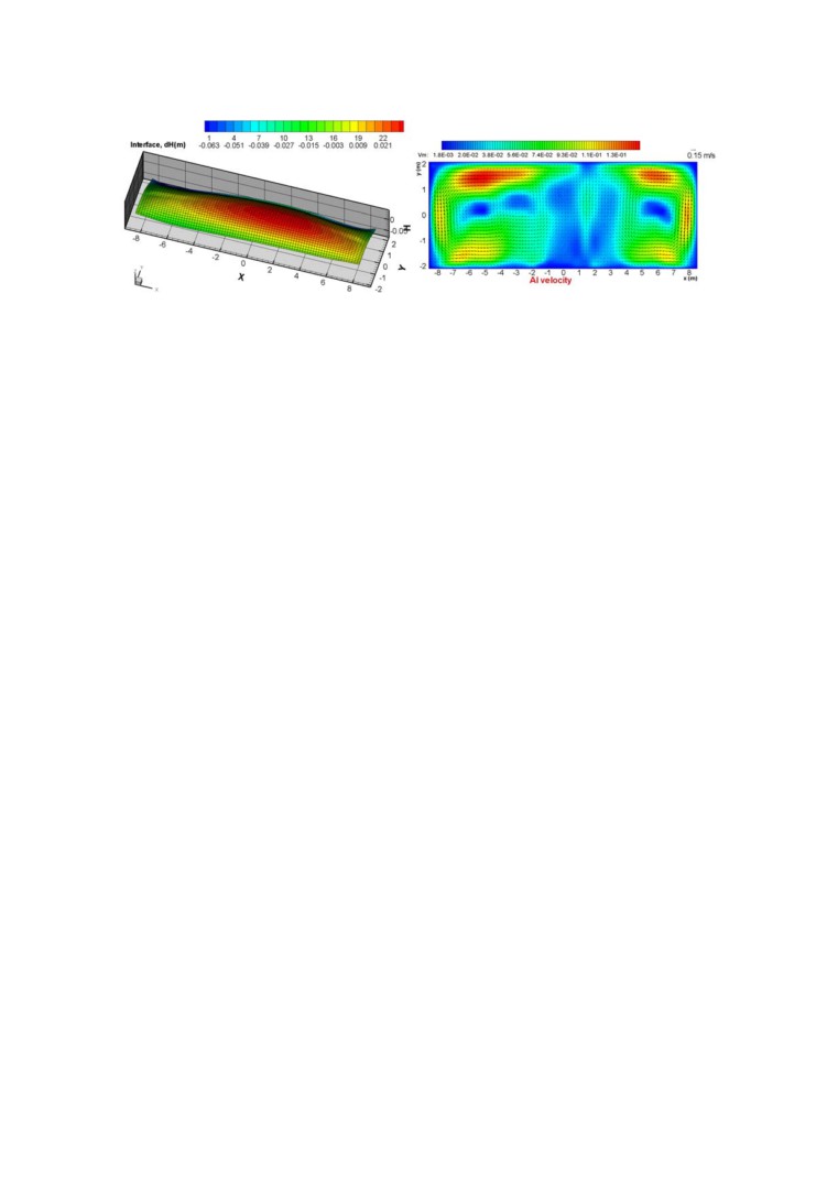
That magnetic field combines with the current density field already presented in Figure 4 to
produce the steady-state bath-metal interface deformation and metal pad steady state metal flow
velocity field presented in Figure 8. The metal flow velocity field is quite unique to this new
busbar configuration. It is characterized by multiple zones of higher speed below the center
channel that would be obvious places to locate the point breaker feeders (PBF). That type of
metal pad flow field should contribute to reduce the sludge accumulation under those PBF.
4
Figure 6. Optimized RCC busbar network concept with alternating risers.
Figure 7. Corresponding Bx and Bz magnetic field components.
Figure 8. Corresponding steady-state bath-metal interface deformation and steady-state
metal pad flow velocity field.
As for the cell energy consumption of that cell design with that new RCC busbar configuration
and that new cathode design, the 500 kA cell presented in [1] that was the starting point of the
current new cell design was predicted to operate at 12.1 kWh/kg (not reported in [1]) with its 87
mV cathode drop, its 265 mV anode drop and its 310 mV busbar drop (not reported in [1]). As
previously presented, by extracting 100 % of the cell current on the downstream side without
increasing the copper collector bar size, the cathode voltage drop is expected to increase to 174
mV. When using a similar busbar weight, the external busbar drop of the revised RCC is
expected to be very similar to the ECC external busbar drop used in [1] so no adjustment is
required for that external ohmic component. This means that that 500 kA cell with copper
collector bars extracting 100 % of its current on the downstream side and using this revised
alternating anode risers RCC busbar configuration is predicted to run at 12.4 kWh/kg while
operating at the same 3.5 cm ACD reported in [1].
5
2.2.
External compensation current (ECC) busbar network
While the idea of taking advantage of copper collector bars to extract 100% of the cell current
on its downstream side came to the author as a way to reduce of busbar weight of its original
RCC busbar configuration, it so happen that the same idea is easily applicable to existing ECC
busbar configurations as well. Figure 9 presents such an ECC busbar configuration.
Figure 9. ECC busbar network concept with 100 % downstream side current exit.
The optimization of the busbar network is very simple as there is only one busbar component,
so the resulting 180 mV of external busbar drop and busbar weight depend only on the choice of
the busbar current density. The metal pad current density is not affected by the change of busbar
network configuration from RCC to ECC as both are perfectly balanced and each are using
components pulling the current from groups of four cathode blocks, so Figure 4 results stand for
this ECC busbar configuration as well.
The resulting magnetic field depends on the current and location of the two compensation
busbars and the location of the return line as it was the case for the results presented in Figure 2
of [1]. The magnetic field presented in Figure 10 was obtained without moving the location of
the return line. The corresponding steady-state bath-metal interface deformation and metal pad
steady-state metal flow velocity field are presented in Figure 11.
Figure 10. Bx and Bz magnetic field components for ECC.
6
Figure 11. Steady-state bath-metal interface deformation and steady-state metal pad flow
velocity field for ECC.
As compared to the previous RCC busbar network case, the change of the predicted cell energy
consumption depends only on the change of the external busbar voltage drop as the cell design
remained exactly the same. Assuming a reduction of 130 mV of the external busbar drop, the
corresponding reduction of the cell energy consumption is 0.4 kWh/kg so that 500 kA cell with
copper collector bars extracting 100 % of its current on the downstream side and using ECC
busbar configuration is predicted to operate at 12 kWh/kg while operating at the same 3.5 cm
ACD reported in [1].
A revised calculation was done using 3.2 cm of ACD instead of 3.5 cm as since 2011,
indications are that ACD has been reduced further in low energy consumption cell prototypes.
At an ACD of 3.2 cm, the predicted cell energy consumption is calculated to decrease to 11.7
kWh/kg Al.
3.
Conclusions
The results presented demonstrated that the usage of copper collector bars with similar sizes as
standard steel collector bars can be used to extract 100 % of the cell current on the cell
downstream size without generating excessive horizontal current in the metal pad or generating
excessive cathode voltage drop.
A 500 kA cell with copper collector bars extracting 100 % of its current on the downstream side
and using a revised alternating anode risers RCC busbar configuration is predicted to be MHD
stable and to run at 12.4 kWh/kg while operating at 3.5 cm ACD and 0.8 A/cm2 of anode
current density.
From [4] it can be extrapolated that a 740 kA or a 1500 kA cell with copper collector bars
extracting 100 % of its current on the downstream side and using the same type of revised
alternating anode risers RCC busbar configuration would work equally well at the same level of
power efficiency.
A 500 kA cell with copper collector bars extracting 100 % of its current on the downstream side
and using a revised ECC busbar configuration is predicted to be MHD stable and to run at 12
kWh/kg while operating at 3.5 cm ACD or 11.7 kWh/kg while operating at 3.2 cm ACD and 0.8
A/cm2 of anode current density.
4.
References
1.
M. Dupuis and V. Bojarevics, Retrofit of a 500 kA cell design into a 600 kA cell
design, ALUMINIUM 87(1/2), 2011, 52-55.
7
2.
Dag Sverre Sæsbøe, Storvik high conductivity anode yoke with copper core,
Proceedings of 33rd International ICSOBA Conference, , Dubai, UAE, 29 November -
1 December 2015, Paper AL23, Travaux No. 44, 717-726.
3.
R. von Kaenel and al., Copper Bars for the Hall-Héroult Process, TMS Light Metals
2016, 903-908.
4.
M. Dupuis, A new aluminium electrolysis cell busbar network concept, Proceedings of
33rd International ICSOBA Conference, Dubai, UAE, 29 November - 1 December
2015, Paper AL21, Travaux No. 44, 699-708.
8