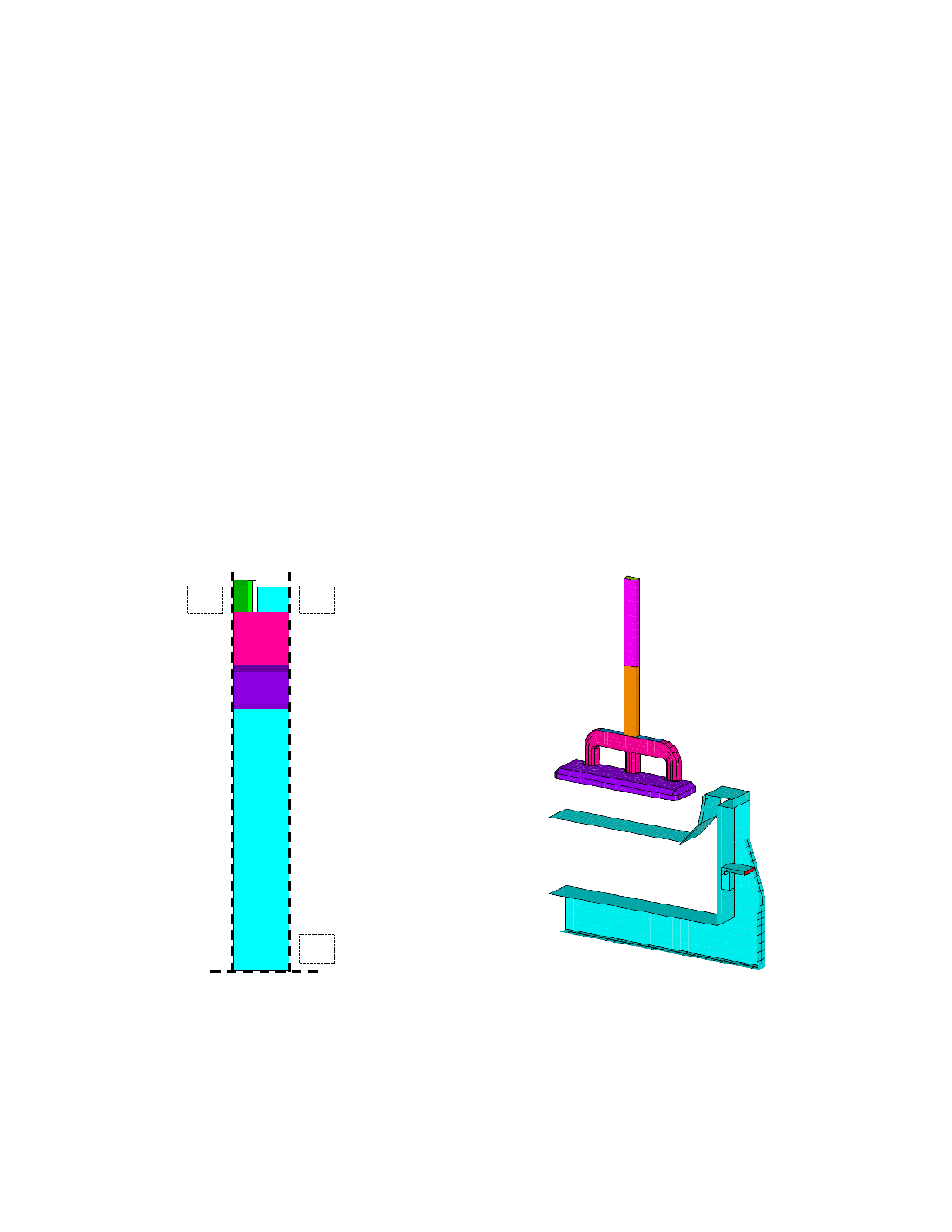
The dashed lines in Figure 5a) represent planes S1, S2 and P3 on which symmetry conditions
could be applied. Planes S1 and S2 are true symmetry planes, and P3 could be considered as
such for the shell and cradle. However, the conditions on the latter are difficult to assess for the
lining: they will depend on the interaction of the lining and the shell along the length of the cell,
and will change with time. It was shown in [2] that the mechanical response of the cathode
blocks changes significantly with the conditions on plane P3, to the extent that it was concluded
that a slice model couldn't be used to predict the stress state of the lining during preheating.
However, for this study and for comparison purposes only, the two extreme cases were
nevertheless considered for the lining on plane P3: symmetry conditions, and free to move.
The thermal boundary conditions for all external surfaces take into account natural convection
and grey body radiation, using well-known semi-empirical correlations and were taken from [5].
They are shown in Figure 5b). The surface of the ramming paste, of the anodes and of the
sidewall is insulated by crushed bath and a convection coefficient of 1 W/m
2
K was used to
approximate this.
S1
P3
S2
Cathode
Block
Paste
Deckplate
S1
P3
S2
S1
P3
S2
Cathode
Block
Paste
Deckplate
a) Slice symmetry planes, top view
b) Convection surfaces
Figure 5 Boundary Conditions.
The anode stem to anode beam contact location is used as the electrical equipotential, and the
current corresponding to a quarter cathode block is forced at the end of the flexible. The
difference in current between the half-anode and the quarter-block is forced on the "dummy"