The brick lining under the cathode block is assumed to have no bending stiffness because in
this design there is a layer of insulating refractory fiber wool that will absorb its thermal
expansion in the horizontal plane. Therefore, the brick lining under the cathode does not
contribute significantly to the mechanical response of the cell during preheating and is
accordingly not solved in the mechanical problem. Conceptually, the cathode block and the pier
are assumed to rest on springs of equivalent stiffness to the underlying brick lining. This is
implemented in the finite element model by using contact mechanics to connect the shell floor to
the bottom of the collector bar, of the cathode block and of the pier. The mechanical mesh is
shown in Figure 3b). Note that the whole slice is solved for temperature (Figure 1).
Bar
Cathode Block
Cast Iron
Air Gap
Bar
Cathode Block
Cast Iron
Air Gap
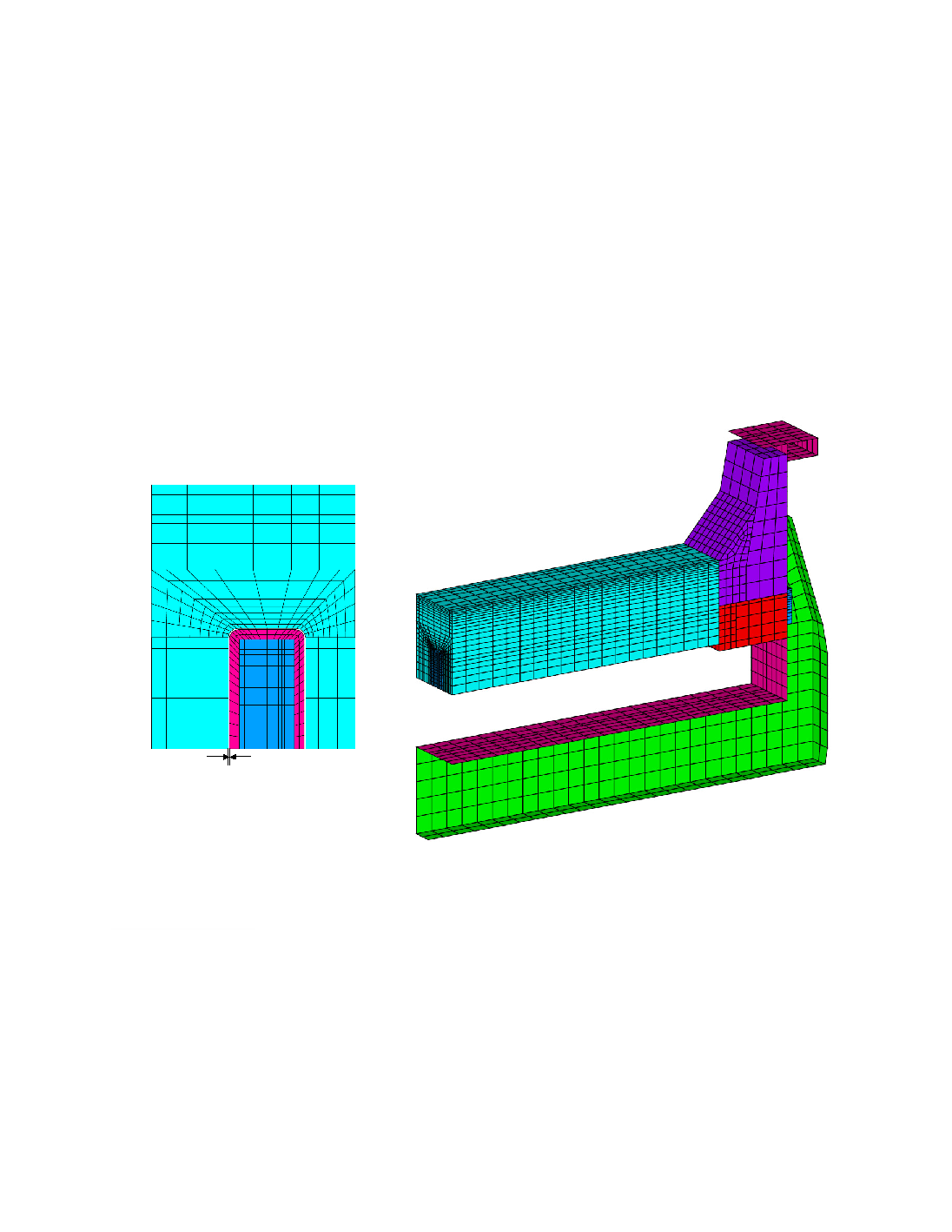
a) Cathode block assembly
b) Mechanical slice mesh
Figure 3 Mechanical Slice Model Details.
Material Properties
The contact resistance at the anode/cathode block interface represents the effect of a 1-inch
coke bed layer of uniform thickness. The effective resistance of the coke bed is temperature-
dependent and inspired from [6]. Potential combustion of the bed is neglected.
The electrical contact resistance at the cast iron-to-cathode block interface is both pressure-
and temperature-dependent is inspired from [12], as shown in Figure 4. A large resistance is