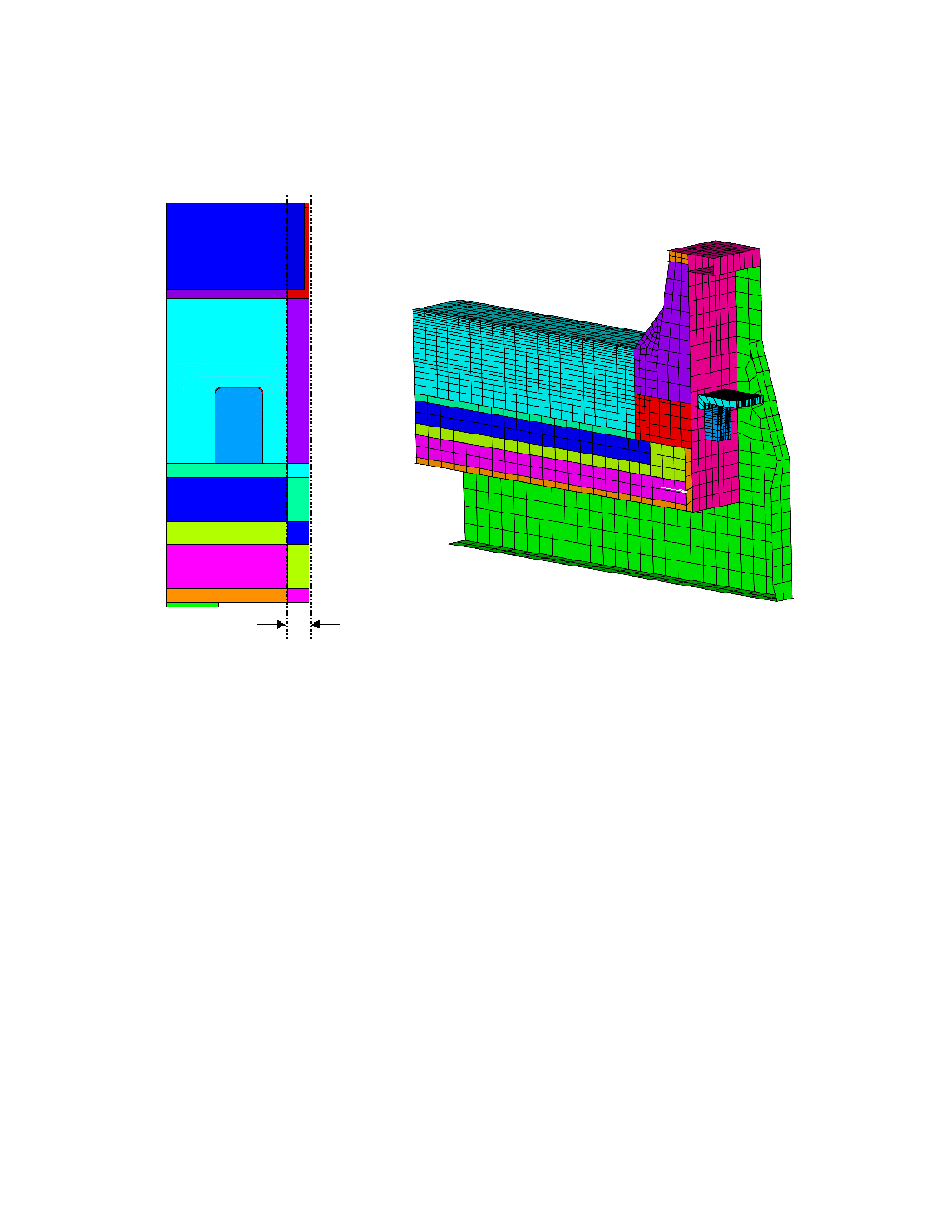
through the cathode block. This concept is shown in Figure 2a). Details of the lining are shown
in Figure 2b).
Cathode
Block
Bar
Anode
Brick lining
"Dummy" Slice
Cathode
Block
Bar
Anode
Brick lining
"Dummy" Slice
Cradle
Deckplate
Shell
Flex
¼ Cathode Block
Brick Lining
Ramming Paste
Side Block
Insulating Wool
Pier
Bar
a) Dummy Slice Concept
b) Cathodic Slice Finite Element Mesh
Figure 2 Cell Slice Model Details.
Contact mechanics is used between different parts of the lining, as can be seen from the non-
concordant mesh at the interfaces between different parts in Figure 2b). An additional thermal
contact resistance (constant or contact pressure-dependent) can be used at an interface, for
example to emulate the effect of a mortar joint. Thermal conductance values were estimated
from [10]. The interfaces are assumed to be non-cohesive, i.e. they cannot sustain a tensile
stress. This is a conservative assumption, given that mortar is used in some places.
The cradles are welded to the shell, and the steel plate thicknesses were estimated from
experience [11]. The collector bar is rodded with cast iron, and a simple geometry was
assumed, as shown in Figure 3a). At ambient temperature, an air gap is present between cast
iron and carbon, and as the assembly heats up, thermal expansion of the parts eliminates this
air gap.