FINITE ELEMENT DEMONSTRATION MODEL
For demonstration purposes, the same cell slice configuration used in [2] of a realistic prebaked
point-fed 300 kA cell design inspired from a VAW publication [4] was used. The thermo-
electrical results, using ANSYS, are presented in [5] for normal steady-state operation.
The slice mesh represents a quarter cathode and its corresponding lining, shell and cradle. The
shell and cradle are discretized using large rotation shell elements while the lining is discretized
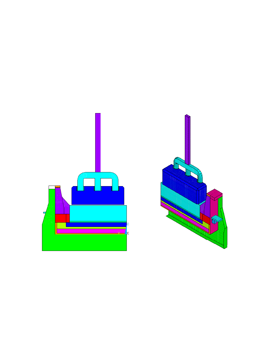
using 3D brick elements. Half an anode was added to the original slice, as shown in Figure 1.
½ Anode
Steel Stubs
Aluminium stem
¼ Cathode Block
½ Anode
Steel Stubs
Aluminium stem
¼ Cathode Block
a) Side view
b) Isometric view
Figure 1 Cell Slice Finite Element Geometry
The mechanical behaviour of the anode assembly is nevertheless neglected and the anode
contributes only to the thermal and electrical fields. The bottom surface of the anode is in
contact with the top surface of the cathode block.
For this cell technology, the number of anodes does not match the number of cathodes such
that half an anode carries more current than a quarter cathode block. Therefore, a "dummy"
thermo-electrical slice is provided to ensure the correct amount of heat and current are flowing