0
20
40
60
80
100
120
140
160
180
0
0.2
0.4
0.6
0.8
1
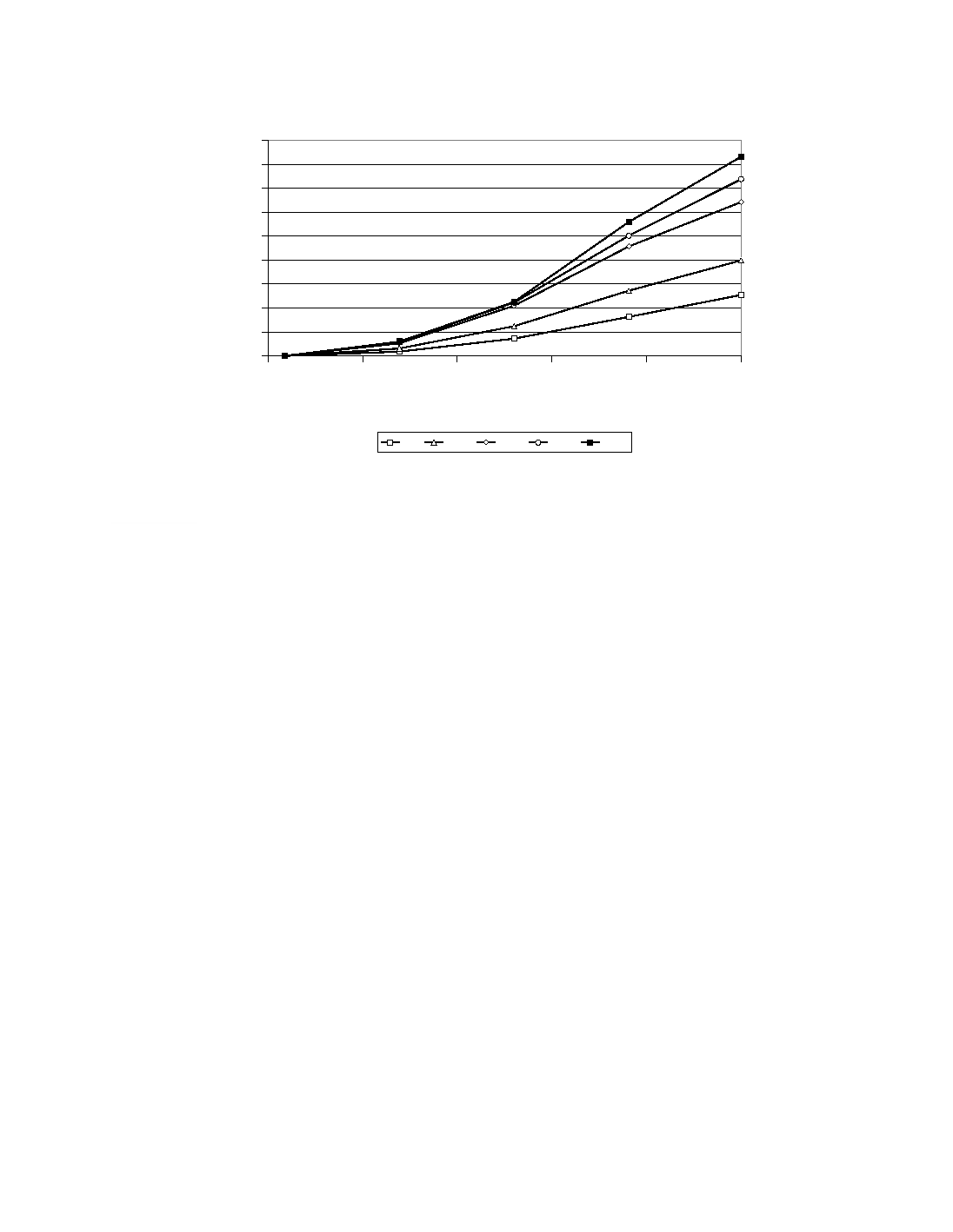
Normalized Distance Along Collector Bar
4h
12h
24h
36h
48h
Figure 14 Collector Bar Current Pickup for Full Line Load Preheating.
Mechanical
The boundary conditions on the lining surface on plane P3 (Figure 5a) have a small impact on
the overall displacements along the width of the cell, but have a large impact on the stress-
strain behaviour of the lining. Two extreme cases were simulated: full symmetry and free to
move. This corresponds respectively to an infinitely rigid shell, and to a perfect expansion joint
along the length of the pot.
As expected, the cathode blocks are bending up and compress the ramming paste. Regarding
potential opening of gaps in the lining, as the cathode block pushes up the paste, a gap opens
between the ramming paste and the pier while the thermally induced deformation of the shell
opens up a gap between the side block and the sidewall near the deckplate (Figure 11). This is
similar to the results previously obtained for thermal bake-out [2].
It was found that the stress distribution in the lining was radically different for the two conditions
on plane P3. For example, the first principal tensile stress is compared in Figure 15 for the case
with shunts and after 25 hours of preheating. This is the moment where the vertical temperature
gradient in the center of the block is maximum for that case, as shown in Figure 10. Note that
the center of the cell is on the right hand side of the cathode block, and the ramming paste
seam is on the left hand side. It can be seen that preventing the transverse expansion of the
cathode block induces a large tensile stress zone originating from the slot wings.